
ASTM D5125-10(2020)e1 Standard Test Method for Viscosity: Understanding Its Purpose and Industry Applications
ASTM D5125-10(2020)e1 is a standardized test method used to measure the viscosity of paints and related materials using ISO flow cups. Viscosity testing helps manufacturers ensure product consistency and proper application characteristics. This test method provides reliable data about how easily a coating will flow during application, which directly impacts its coverage, thickness, and overall performance.

When you need to evaluate paints, varnishes, or similar coatings, this standard offers a practical approach to quality control. The ISO flow cup method measures the time it takes for a specific volume of material to flow through a calibrated orifice under controlled conditions. The results help formulators adjust compositions to meet specific requirements for brushing, spraying, or other application methods.
Unlike rotational viscometers or other testing approaches, the ISO flow cup method is relatively simple to implement in both laboratory and production environments. You can quickly assess whether your paint products meet specifications before they leave your facility, helping to prevent costly application problems in the field.
Belangrijkste punten
- ASTM D5125 measures paint viscosity using ISO flow cups to predict application performance and ensure product consistency.
- The test provides critical data for quality control in paint manufacturing and helps formulators adjust compositions to meet specific requirements.
- ISO flow cup testing offers a simpler alternative to other viscosity measurement methods while still delivering reliable results for paint and coating products.
Understanding ASTM D5125-10(2020)e1

This standard provides a reliable method for measuring the viscosity of paints and related materials using ISO flow cups. It serves as a critical quality control tool in manufacturing and application processes for coatings.
Scope and Purpose of the Standard
ASTM D5125 specifically covers the determination of flow time (viscosity) for Newtonian and near-Newtonian paints, coatings, and related products. The standard uses ISO capillary flow cups with different orifice diameters (3mm, 4mm, 5mm, or 6mm) to accommodate various material viscosities.
This test method is particularly important in production environments where consistent product quality is essential. By measuring viscosity, manufacturers can ensure their paints and coatings will perform as expected during application.
For non-Newtonian liquids that exhibit shear-thinning or thixotropic behavior, this standard isn’t appropriate. In those cases, ASTM D2196 should be used instead.
Historical Context and Development
ASTM D5125 was originally adopted in 2010 and later reapproved in 2020 with editorial changes, as indicated by the “e1” designation. This standard represents an evolution in viscosity testing methods for coatings.
The development of this standard addressed the need for international harmonization in testing procedures. ISO flow cups provide consistency across global markets, allowing manufacturers and users worldwide to speak the same language regarding viscosity measurements.
Prior to standardized methods like D5125, viscosity testing varied significantly between regions and manufacturers. This created challenges for quality control and product specifications.
Key Definitions and Terminology
Viscositeit: The resistance of a liquid to flow. In this standard, it’s measured indirectly through flow time.
Newtonian fluids: Materials whose viscosity remains constant regardless of the force applied. Many simple paints fall into this category.
Near-Newtonian fluids: Materials that closely approximate Newtonian behavior under the test conditions.
ISO flow cups: Standardized measurement devices with precisely calibrated orifices through which the test material flows.
Flow time: The time required for a specific volume of material to flow through the cup’s orifice, measured in seconds.
When interpreting results, you should understand that higher flow times indicate higher viscosities. Temperature significantly affects results and must be carefully controlled during testing.
Specific Use and Industrial Importance

ASTM D5125-10(2020)e1 serves as a cornerstone test method in the coatings industry for measuring viscosity using ISO flow cups. This standardized approach enables manufacturers and quality control teams to ensure consistent product performance across production batches.
Applications in Paints and Related Materials
The test method specifically addresses Newtonian and near-Newtonian paints and coatings. These include architectural paints, industrial coatings, automotive finishes, and marine coatings where flow properties directly impact application quality.
You can use this test to determine both package viscosity (as manufactured) and application viscosity (after thinning). This distinction is crucial because products must maintain proper viscosity during storage while achieving optimal flow during application.
For manufacturers, this test provides data that correlates directly with real-world application behaviors like:
- Brush and roller pickup and release
- Spray application characteristics
- Sagging and leveling tendencies
- Film thickness consistency
The method works particularly well for quality control in production environments where quick, reliable viscosity measurements guide formulation adjustments.
Relevance to Quality Assurance Processes
In quality assurance, D5125 serves as a repeatable, standardized approach to viscosity verification. You can implement this test at multiple stages of production to maintain tight quality control.
The test helps you identify batch-to-batch variations that might otherwise go undetected. Early detection of viscosity drift prevents costly production issues and customer complaints.
Quality teams value this method because:
- It requires minimal specialized training
- Equipment is relatively inexpensive
- Tests can be performed quickly (typically under 5 minutes)
- Results are reproducible across different operators
You can establish viscosity specifications with acceptable ranges based on this test, creating clear pass/fail criteria for production batches. This objectivity removes subjective assessments of flow properties.
Critical Role in Product Performance
Viscosity directly influences how coatings perform in real-world applications. Through D5125 testing, you can predict and control these performance attributes.
For architectural paints, proper viscosity ensures even coverage and hiding power. Industrial coatings rely on precise viscosity for corrosion protection and adhesion to difficult substrates.
The test helps you balance competing requirements:
- Too thin: runs, sags, poor hiding
- Too thick: brush marks, poor leveling, difficult application
By maintaining viscosity within specification, you prevent common field complaints like inconsistent appearance, poor durability, and application difficulties. This translates to fewer warranty claims and greater customer satisfaction.
The test also supports formulation development, helping you understand how ingredient changes affect application properties before scaling to full production.
Materials and Products Covered by the Standard

ASTM D5125 specifically addresses viscosity measurement for certain types of liquid coating materials. This standard applies to both Newtonian and near-Newtonian liquids that flow predictably through ISO capillary flow cups.
Types of Paints Evaluated
This standard primarily evaluates architectural and industrial paints with Newtonian or near-Newtonian properties. These include:
- Water-based paints: Latex, acrylic, and vinyl paints used for walls and trim
- Oil-based paints: Alkyd and enamel formulations for various surfaces
- Specialty paints: Marine paints, automotive finishes, and certain industrial coatings
You can use this test method for paints in different stages of production—from raw materials to finished products. The standard is particularly useful for determining package viscosity (as shipped) and application viscosity (ready for use).
Other Coatings and Related Materials
Beyond paints, D5125 covers a range of additional coating materials:
- Varnishes and lacquers for wood finishing
- Primers and sealers used before paint application
- Clear coats for protective finishing
- Some adhesives with appropriate flow properties
The standard specifically notes that non-Newtonian materials (those that are shear-thinning or thixotropic) should instead be tested using ASTM D2196. Materials that change viscosity significantly under different shear rates aren’t suitable for ISO flow cup testing.
This test method also has applications in international regulations, where it may be used alongside flashpoint tests to determine hazard classifications for viscous liquids during transport.
Principles Behind ISO Flow Cup Viscosity Measurement

ISO flow cups provide a standardized method for measuring the viscosity of paints and coatings. These simple yet effective tools rely on the relationship between flow time and viscosity to help manufacturers ensure product consistency.
Basic Concept of Kinematic Viscosity
Kinematic viscosity measures a fluid’s resistance to flow under gravity. It represents the ratio of dynamic viscosity to density of the fluid. For paints and coatings, this property directly affects application characteristics.
When you measure kinematic viscosity using flow cups, you’re observing how quickly a specific volume of liquid flows through a calibrated orifice. The time it takes for this flow to occur correlates with the viscosity.
Newtonian fluids maintain constant viscosity regardless of applied force. ASTM D5125 is specifically designed for these fluids and near-Newtonian materials. For non-Newtonian fluids (those that change viscosity under stress), other test methods like ASTM D2196 are more appropriate.
How ISO Flow Cups Work
ISO flow cups consist of a cup with a precisely machined orifice at the bottom. You fill the cup with your paint or coating to a specified level. When you remove a finger from the orifice, liquid begins to drain.
The time (in seconds) between releasing the orifice and the first break in the fluid stream is your measurement. Different cup sizes (with various orifice diameters) accommodate different viscosity ranges:
- Cup #3: Low viscosity materials
- Cup #4: Medium viscosity materials
- Cup #5: Higher viscosity materials
Temperature significantly affects results, so testing must occur at controlled conditions (typically 25°C). The cup must be clean, level, and free from vibration for accurate measurements.
Interpreting Test Results and Implications

Understanding the viscosity values obtained through ASTM D5125 testing provides crucial insights into paint performance. These results directly affect how paints apply and function in real-world conditions.
What Viscosity Values Indicate
Viscosity measurements from ISO flow cups are reported in seconds. Higher numbers indicate thicker paints, while lower numbers mean thinner consistency.
For most architectural paints, optimal flow times range between 20-30 seconds using a #4 cup. Industrial coatings might require longer flow times of 30-60 seconds for proper application.
When your test results show inconsistent values between batches, this signals potential quality control issues. Significant deviations (>10%) from manufacturer specifications may lead to application problems.
Temperature greatly affects results. A 5°F change can alter viscosity readings by 10-15%. Always note the temperature during testing and adjust expectations accordingly.
Impact on Application and Performance
Viscosity directly influences how you apply paint and its final appearance. Paints with proper viscosity spread evenly and adhere well to surfaces.
Too high viscosity (long flow times) can cause:
- Difficult brush or roller application
- Poor leveling and visible brush marks
- Reduced coverage area per gallon
- Potential sagging on vertical surfaces
Too low viscosity (short flow times) often leads to:
- Excessive dripping during application
- Poor hiding power and multiple coats needed
- Reduced film thickness
- Potential for runs and sags
For spray applications, you need specific viscosity ranges based on equipment type. HVLP sprayers typically require 20-25 seconds in a #4 cup, while airless sprayers can handle 25-35 seconds.
Example Applications and Typical Samples

ISO flow cups used in ASTM D5125 test methods have wide applications across industries where paint and coating viscosity measurement is critical. The test provides reliable viscosity data that helps manufacturers maintain quality control and ensure proper application characteristics.
Case Study: Architectural Paints
A major paint manufacturer used ASTM D5125 to develop a new line of low-VOC interior wall paints. Using a 4 mm ISO flow cup, they tested formulations at various stages of development. The target flow time was 45-60 seconds, which corresponded to the optimal application viscosity for both brush and roller application.
When a batch showed inconsistent results (flow times varying by more than 5 seconds), the quality control team identified improper dispersant levels as the cause. After adjusting the formula, the flow times stabilized, resulting in a product with excellent application properties.
This case demonstrates how the test method helps identify issues during production that might otherwise lead to customer complaints about paint that’s too thick or thin.
Common Sample Types in Industry Settings
You’ll find ASTM D5125 commonly used with these sample types:
- Architectural coatings: Interior and exterior paints, primers, and sealers
- Industrial finishes: Equipment coatings, metal protection systems
- Automotive paints: Both OEM and refinish products
- Marine coatings: Hull paints and anti-fouling systems
For water-based latex paints, the 4 mm or 5 mm cup is typically used. Thicker coatings like high-solids epoxies might require the 6 mm cup, while thin sealers work best with the 3 mm cup.
Many manufacturers establish viscosity specifications using this method for both incoming raw materials and finished products. The simplicity of the test makes it ideal for production floor quality checks.
Best Practices for Test Implementation
Proper implementation of ASTM D5125 requires careful attention to detail and consistent technique. Following established best practices ensures reliable viscosity measurements with ISO flow cups.
Sampling and Preparation Considerations
Always collect a representative sample of the paint or coating material. Stir the sample thoroughly but gently to ensure uniformity without introducing air bubbles.
Strain the sample through a fine mesh filter (100-150 mesh) to remove any particles that could clog the orifice. This step is crucial for accurate results.
Temperature control is essential. Allow samples to stabilize at the test temperature (typically 23°C ± 2°C) for at least 2 hours before testing. Use a water bath if necessary to maintain consistent temperature.
Record the ambient conditions, as temperature and humidity can affect flow behavior. Test samples should be free from air bubbles, which can disrupt flow patterns.
Key Factors Affecting Measurement Accuracy
Select the appropriate cup-orifice combination based on the expected viscosity range. Use smaller orifices (3-4mm) for lower viscosity materials and larger ones (5-6mm) for higher viscosity materials.
Position the flow cup perfectly level using a bubble level. Even slight tilting can significantly alter flow times.
Cup cleanliness is critical. Residue or contamination can change orifice dimensions and affect results. Clean cups thoroughly with appropriate solvents and dry completely between tests.
Practice consistent timing technique. Start the stopwatch immediately when the flow begins and stop it at the first break in the stream.
Perform at least three measurements for each sample and calculate the average. Results should be within ±5% to be considered valid and repeatable.
Comparison to Other Viscosity Test Methods
ASTM D5125 offers distinct advantages over other viscosity measurement methods. While all viscosity tests measure fluid flow characteristics, each method brings different strengths to specific applications and material types.
Distinctions From ASTM D1200
ASTM D1200 uses Ford cups while D5125 employs ISO flow cups. The key difference lies in cup geometry and orifice design. Ford cups have a specific straight-bore orifice length-to-diameter ratio, while ISO cups feature a more complex orifice design with an initial cylindrical section followed by a conical section.
ISO cups (D5125) offer better precision for certain coating formulations, particularly water-based and low-viscosity systems. The calibration procedures also differ between methods. D5125 requires more stringent calibration with certified reference materials.
For global markets, D5125 aligns with international standards like ISO 2431, making it preferable for companies selling products worldwide. You’ll find D5125 particularly useful when consistency with European specifications is needed.
Differences With Brookfield Viscosity Methods
Brookfield methods (like ASTM D2196) use rotational viscometers that measure torque required to rotate a spindle in the fluid. This differs fundamentally from D5125’s gravity-flow principle through a calibrated orifice.
Brookfield methods excel at measuring non-Newtonian fluids that exhibit shear-thinning or thixotropic behavior. D5125, however, is specifically designed for Newtonian or near-Newtonian paints and coatings.
You can obtain complete viscosity profiles at different shear rates with Brookfield methods. D5125 provides a single-point measurement that represents application viscosity.
For quality control purposes, Brookfield methods require more expensive equipment but offer greater versatility. D5125 provides simpler, faster testing with more affordable equipment for everyday production environments.
Summary of Unique Advantages
D5125 offers excellent reproducibility for Newtonian fluids with a coefficient of variation typically below 3% between laboratories. This makes it ideal for specification compliance testing.
The test equipment is portable and requires minimal maintenance compared to electronic viscometers. You can easily implement it in field conditions or production floors.
D5125 correlates well with application properties like brush drag, sag resistance, and film build. This makes it particularly valuable for predicting how a coating will perform during application.
For international trade, D5125’s alignment with ISO standards simplifies certification processes. Using this method can reduce regulatory barriers when selling products in multiple countries.
Frequently Asked Questions
The ASTM D5125-10(2020)e1 standard provides important guidelines for measuring viscosity of paints and coatings using ISO Flow Cups. These cups help determine flow properties essential for quality control and product performance.
What is the purpose of the ASTM D5125-10(2020)e1 standard test method in measuring viscosity?
The ASTM D5125-10(2020)e1 standard measures the flow time (viscosity) of paints and related coatings. This method specifically uses ISO Flow Cups to determine how quickly materials flow through a standardized orifice.
The purpose is to provide a consistent, repeatable way to assess flow behavior. This helps manufacturers ensure their products have the right consistency for application.
By standardizing the measurement process, the test allows for quality control checks and comparison between different batches or products.
Why is the ASTM D5125-10(2020)e1 test method considered significant in industrial applications?
This test method is crucial for quality control in paint and coating manufacturing. It helps ensure products flow properly when applied by brush, spray, or other methods.
Consistent viscosity directly affects product performance characteristics like coverage, leveling, and film thickness. Without proper viscosity testing, products might fail to meet performance requirements.
The method’s standardization allows manufacturers to communicate viscosity specifications clearly to suppliers and customers. This common language helps maintain quality across the supply chain.
What types of materials and products are typically subject to viscosity testing using the ISO Flow Cups as per ASTM D5125-10(2020)e1?
Paints and varnishes are the primary materials tested using this method. This includes both water-based and solvent-based formulations.
Inks, particularly those used in printing applications, are commonly tested for flow properties. Their viscosity directly impacts print quality and transfer characteristics.
Other coatings such as sealants, primers, and specialty finishes also benefit from this testing method. The test works best with Newtonian and near-Newtonian fluids that flow predictably.
What are the fundamental principles governing the viscosity test according to the ASTM D5125-10(2020)e1 standard?
The test operates on gravity-driven flow principles. A cup with a precisely sized orifice at the bottom is filled with the test material.
The time it takes for the material to flow through the orifice is measured in seconds. This flow time correlates with the material’s viscosity – longer times indicate higher viscosity.
Temperature must be carefully controlled during testing since viscosity changes significantly with temperature variations. Standard testing occurs at 25°C (77°F) unless otherwise specified.
How do the results from the ASTM D5125-10(2020)e1 viscosity test influence material or product evaluation?
Test results directly determine if products meet application specifications. Materials with incorrect viscosity may be too thick to spray or too thin to provide adequate coverage.
Results help predict how coatings will perform during application. Proper viscosity ensures coatings will level correctly and form films of appropriate thickness.
Manufacturers use these test results to make formulation adjustments. If viscosity is too high or low, additives can be incorporated or production parameters modified to achieve target properties.
What are the best practices for conducting and interpreting results from the ISO Flow Cups viscosity test as described in ASTM D5125-10(2020)e1?
Always calibrate your flow cups regularly using reference oils with known viscosities. This ensures measurement accuracy and repeatability.
Control the testing environment temperature carefully. Even small temperature variations can significantly affect viscosity measurements.
Take multiple readings and calculate the average for more reliable results. Three measurements are typically recommended.
Clean cups thoroughly between tests to prevent contamination. Residue from previous tests can alter flow characteristics and lead to inaccurate readings.
When interpreting results, compare them to established specifications for your specific product. Remember that viscosity requirements vary based on application method and intended use.
- Gepubliceerd in Wetenschap & Onderzoek
ASTM B212-21 Standard Test Method for Apparent Density: Essential Guide for Metal Powder Testing
Metal powder testing is a critical step in manufacturing processes across many industries. One key test that manufacturers rely on is ASTM B212-21, a standard method for measuring the apparent density of free-flowing metal powders. This test uses a specific tool called the Hall Flowmeter Funnel to determine how densely metal powder particles pack together when allowed to flow naturally.

The apparent density measurement tells you how much space a specific weight of powder will occupy, which directly impacts how you’ll need to handle the material in production settings. When working with metal powders for applications like powder metallurgy, additive manufacturing, or thermal spray coatings, this property affects everything from storage requirements to final product quality.
Testing metal powders with the Hall Flowmeter Funnel gives consistent, reliable results that help ensure quality control across different batches. For example, when testing aluminum powder for 3D printing, variations in apparent density might signal issues with particle size distribution or morphology that could affect the final printed part. Similarly, copper or steel powders used in sintering processes require precise density measurements to predict how they’ll behave during compaction and sintering.
Belangrijkste punten
- Apparent density testing with the Hall Flowmeter Funnel measures how metal powders pack naturally, affecting production requirements and final product quality.
- The test applies only to free-flowing metal powders that can move through the funnel without assistance, making it ideal for quality control in powder manufacturing.
- Results from ASTM B212-21 testing help you predict how powders will perform in various applications like 3D printing, sintering, and thermal spray coatings.
Overview of ASTM B212-21 Standard Test Method

ASTM B212-21 provides standardized procedures for measuring apparent density of free-flowing metal powders using the Hall Flowmeter Funnel. This internationally recognized test method helps you determine how much powder mass will fill a specific volume, which is crucial for powder metallurgy applications.
Purpose and Scope of ASTM B212-21
The primary purpose of ASTM B212-21 is to establish a consistent method for measuring the apparent density of metal powders that flow freely. This standard applies specifically to powders that can pass through the Hall Flowmeter Funnel without external assistance.
The test measures how powder particles pack together under gravity alone, without applied pressure. This information helps you predict how powder will behave during die filling operations in manufacturing processes.
The scope includes various metal powders used in powder metallurgy, including iron, copper, aluminum, and their alloys. The standard provides detailed instructions for equipment specifications, calibration requirements, and proper testing procedures to ensure reliable results.
Significance of Apparent Density in Metal Powder Characterization
Apparent density directly relates to the mass of powder that will fill a fixed volume die cavity in manufacturing processes. This property influences several important aspects of powder metallurgy:
- Production efficiency – Higher apparent density typically means more efficient material usage
- Component quality – Density affects final part properties including strength and porosity
- Process control – Consistent density measurements help maintain manufacturing standards
The measurement is reported in g/cm³ to the nearest 0.01 g/cm³, providing a precise value for quality control purposes. Apparent density varies between powder types and can be influenced by particle size, shape, and distribution.
When testing different powders, you’ll notice that spherical particles typically show higher apparent density than irregular shapes due to their efficient packing characteristics.
Role of ASTM Standards in Powder Metallurgy
ASTM International standards like B212-21 provide crucial frameworks for ensuring consistency across the powder metallurgy industry. These standards enable you to:
- Compare products from different suppliers using identical testing methods
- Maintain quality control with recognized benchmarks
- Meet regulatory and customer requirements with documented procedures
Standardization helps eliminate variables that could affect test results, such as equipment differences or procedural variations. When you follow ASTM B212-21, you’re using methods that have been validated through collaborative testing among industry experts.
The powder metallurgy industry relies on these standards to facilitate clear communication between suppliers and customers. They form the foundation for material specifications and help advance the field through consistent testing methodologies.
Principle of the Hall Flowmeter Funnel Apparatus

The Hall Flowmeter Funnel is a key instrument used to determine the apparent density of free-flowing metal powders. This apparatus helps measure how metal powder flows and fills a space, which is crucial for predicting manufacturing outcomes.
Description of the Hall Flowmeter Funnel
The Hall Flowmeter Funnel consists of a standardized conical funnel with a calibrated orifice. It has a specific shape designed to allow metal powders to flow consistently through the opening. The funnel includes a valve or stopper at the bottom that controls the powder flow.
When you use this apparatus, you place it directly above a density cup. The funnel’s design ensures that powder flows at a controlled rate, creating consistent testing conditions.
The standard specifies exact dimensions for the funnel. These precise measurements help ensure that test results remain comparable across different laboratories and testing situations.
Fixed Volume Die Cavity Concept
The density cup used with the Hall Flowmeter Funnel has a nominal capacity of 25 cm³. This cup represents a fixed volume die cavity in powder metallurgy applications.
When you measure apparent density, you’re essentially determining how much powder mass will fill a specific volume. This relationship directly correlates to how powder will behave when filling actual die cavities during manufacturing processes.
The density cup must meet strict tolerance requirements (25 cm³ ± 0.03). If your cup falls outside these tolerances, you should replace it to maintain testing accuracy.
The actual volume of each cup should be verified using Test Method B873 to ensure precision in your measurements.
Physical Characteristics Affecting Flow
Several physical characteristics of metal powders influence how they flow through the Hall Flowmeter Funnel. Particle size, shape, and distribution play significant roles in determining flow behavior.
Surface roughness affects how particles interact with each other and with the funnel walls. Smoother particles typically flow more freely than irregular ones.
Moisture content can dramatically impact flow properties. Even small amounts of moisture can cause particles to stick together, reducing flowability and affecting your apparent density measurements.
Chemical composition and surface oxidation may also influence flow characteristics. Some metal powders are more susceptible to these effects than others.
When you test different metal powder types, you’ll notice that materials like spherical atomized powders generally flow better than irregular or dendritic powders.
Test Procedure and Calculations
The ASTM B212-21 test procedure involves several precise steps to determine the apparent density of free-flowing metal powders. This standardized method ensures consistent results across different testing facilities when measuring how metal powder fills a given volume.
Sample Preparation and Handling
Before testing, you must properly prepare your metal powder sample. Ensure your sample is representative of the entire batch by using proper sampling techniques. The powder must be free-flowing enough to pass through the Hall Flowmeter Funnel without assistance.
Store the powder in a sealed container to prevent moisture absorption or contamination. Handle the powder carefully to avoid compaction before testing, as this can affect apparent density results.
For accurate testing, condition your samples in a controlled environment (typically 23 ± 5°C and 50 ± 10% relative humidity) for at least 24 hours before testing. This equilibration period ensures consistent moisture content.
The powder amount should be sufficient for testing—typically 50-100g depending on the powder type.
Measurement of Apparent Density
To measure apparent density, you’ll use the Hall Flowmeter Funnel and a density cup of known volume. Begin by placing a clean, dry funnel in its stand. The bottom of the funnel should be 25 ± 0.5 mm above the top of the density cup.
Close the funnel’s orifice with your finger or a suitable stopper. Pour approximately 50g of powder into the funnel without compacting it.
Place the density cup (with known volume) directly under the funnel. Remove your finger to allow the powder to flow freely into the cup. The powder should form a heap above the cup.
When the powder stops flowing, carefully level the excess powder using a non-magnetic straight edge. Make a single pass across the top of the cup without pressing down or disturbing the powder bed.
Determination of Mass and Volume
The density cup has a precisely calibrated volume, typically 25 cm³. Measure and record this volume accurately before testing.
After leveling the powder in the cup, carefully weigh the filled cup on an analytical balance with precision of at least 0.01g. Subtract the weight of the empty cup to determine the powder mass.
For best results, repeat this measurement at least three times with fresh powder samples. The variability between measurements should be less than 0.4% for most metal powders.
Record all mass and volume measurements in your lab notebook. The density cup volume should be calibrated periodically to ensure accuracy.
Calculation Using Inch-Pound and SI Units
Calculate the apparent density by dividing the powder mass by the cup volume. The standard unit for apparent density is g/cm³.
For SI units:
Apparent Density (g/cm³) = Powder Mass (g) / Cup Volume (cm³)
For inch-pound units:
Apparent Density (lb/in³) = Powder Mass (lb) / Cup Volume (in³)
To convert between units:
- 1 g/cm³ = 0.0361 lb/in³
- 1 lb/in³ = 27.68 g/cm³
Report your results to three significant figures. Include the average of multiple determinations and the standard deviation if required by your testing protocol.
Factors Affecting Results and Test Method Limitations
Several variables can influence the accuracy and reliability of apparent density measurements when using the ASTM B212-21 method. Understanding these factors helps ensure proper testing procedures and interpretation of results.
Influence of Powder Composition
Powder composition significantly affects apparent density measurements. Particles with irregular shapes typically result in lower apparent density values compared to spherical particles, which pack more efficiently.
Metal powders with varying particle size distributions may flow differently through the Hall funnel, affecting measurement consistency. Fine particles tend to have stronger interparticle forces, potentially causing agglomeration and irregular flow.
When testing alloy powders, the relative density of constituent metals impacts results. For example, titanium-aluminum mixtures will show different apparent densities than pure copper or iron powders due to their inherent material densities.
Compositional homogeneity is crucial for reliable results. Non-uniform mixtures may segregate during handling or testing, leading to measurement variations between samples of the same batch.
Effects of Moisture, Oils, and Other Additives
Moisture is particularly problematic in apparent density testing. Even small amounts can cause metal particles to stick together, impeding proper flow through the funnel and resulting in inconsistent measurements.
Oils and lubricants, whether intentionally added or as contaminants, significantly alter flow characteristics. Stearic acid and stearates, commonly used as die wall lubricants, can coat particles and reduce interparticle friction, potentially increasing flowability but changing apparent density.
Waxes and polymer additives used as binders in powder metallurgy processes affect both flow and packing behavior. These additives can bridge between particles, altering the natural packing arrangement and density measurements.
Temperature and humidity conditions during testing can affect moisture content. You should conduct testing in controlled environments to minimize these variables.
Free-Flowing Versus Non-Free-Flowing Powders
ASTM B212-21 is specifically designed for free-flowing metal powders. Non-free-flowing powders cannot pass through the Hall funnel without assistance, making this method unsuitable for such materials.
Fine powders below 20 microns often demonstrate poor flowability due to increased surface area and stronger interparticle forces. These powders may require alternative testing methods like the Scott Volumeter (ASTM B329).
Mixed powders with components of significantly different densities may segregate during handling, leading to inconsistent flow and unreliable measurements. You should thoroughly mix samples immediately before testing.
Shape factor variations between powder types affect both flowability and packing efficiency. Highly irregular or dendritic particles typically show poorer flow characteristics than atomized spherical powders, potentially limiting test applicability.
Interpretation and Application of Test Results
The apparent density values obtained through ASTM B212-21 provide critical insights into how metal powders will behave during manufacturing processes. These results help predict filling characteristics and final part properties in powder metallurgy operations.
Performance of Metal Powders in Industrial Applications
Apparent density directly relates to how metal powders fill die cavities in pressing operations. Higher density powders typically result in greater mass within fixed volume dies, affecting final part weight and dimensions.
When working with aluminum powders, an apparent density of 1.0-1.3 g/cm³ indicates good flowability for applications like metal injection molding. For iron powders used in structural components, optimal apparent density ranges from 2.5-3.0 g/cm³.
The test results help you predict:
- Filling consistency in automated powder handling systems
- Compaction behavior during pressing operations
- Sintering characteristics and final part density
Test values showing significant deviation from specification might signal processing issues or raw material inconsistencies that could affect your final product quality.
Use in Quality Control and Research
Apparent density testing serves as a fundamental quality control benchmark in metal powder production and usage. You can establish acceptable density ranges for incoming materials by correlating test results with processing success.
Many manufacturers implement Statistical Process Control (SPC) using apparent density data to:
- Monitor batch-to-batch consistency
- Identify production drift before failures occur
- Validate new powder suppliers
In research settings, apparent density measurements help you understand relationships between powder physical characteristics and processing parameters. For example, when developing new titanium alloy powders, tracking apparent density changes with particle size distribution modifications provides insights into optimized mixing ratios.
Test results also support development of novel powder metallurgy techniques by establishing baseline properties that correlate with successful processing windows.
Regulatory Considerations and International Relevance
ASTM B212-21 has significant implications for global trade and manufacturing regulations. This standard must be understood within the broader international context of powder metallurgy specifications and compliance requirements.
Alignment with International Standards and Practices
The ASTM B212-21 test method aligns with several international standards for metal powder testing. You should note that ISO has complementary standards that address similar testing parameters for apparent density measurements.
When your facility exports metal powders, understanding these alignments helps ensure your products meet global requirements. Many countries recognize ASTM standards as acceptable technical references in their regulatory frameworks.
European regulations often reference both ASTM and ISO standards for metal powder characterization. This dual recognition simplifies your compliance efforts when shipping products to multiple markets.
Regional variations in implementation do exist, so you should verify specific requirements for your target markets.
Role in Technical Barriers to Trade and WTO Compliance
WTO agreements aim to prevent technical standards from becoming unnecessary trade barriers. ASTM B212-21 serves as a recognized reference method that helps you avoid technical barriers to trade (TBT).
When you use internationally accepted test methods like B212-21, you reduce the need for redundant testing when entering different markets. This saves both time and resources while maintaining regulatory compliance.
The standard’s transparent methodology supports WTO principles by providing clear specifications that all trading partners can understand and implement. This transparency helps prevent discriminatory practices in international trade.
Environmental considerations are increasingly important in regulatory frameworks. While B212-21 focuses on physical properties, your testing program should also address environmental aspects of powder handling and disposal.
Examples of Testing Various Metal Powders
Testing various metal powders using ASTM B212-21 reveals interesting differences in apparent density values that directly impact powder metallurgy applications. The following examples demonstrate how this test method applies to different types of metal powders and their mixtures.
Testing Pure Metal Powders
When testing pure copper powder, you’ll typically find apparent density values ranging from 2.5-3.5 g/cm³, depending on particle size and shape. Spherical copper particles generally yield higher apparent density values than irregular ones.
Iron powder often exhibits apparent density values between 2.7-3.3 g/cm³. Testing shows that water-atomized iron powder typically has lower apparent density than gas-atomized powder due to its irregular morphology.
For aluminum powder, apparent density values are considerably lower (1.0-1.4 g/cm³) due to aluminum’s lower specific gravity. Testing reveals that finer aluminum powders tend to have lower apparent density due to increased surface area and inter-particle friction.
Titanium powder testing presents interesting results with apparent density values of 1.5-2.5 g/cm³. The flow characteristics through the Hall funnel are notably affected by particle morphology.
Apparent Density of Mixed and Alloyed Powders
When you test mixed powders, such as bronze (copper-tin), you’ll observe apparent density values between 3.0-4.5 g/cm³. The ratio of components significantly affects the test results.
Pre-alloyed stainless steel powders typically show apparent density values of 2.8-3.8 g/cm³. Testing reveals that 316L stainless steel powder commonly has lower apparent density than 304L powder due to differences in composition and processing.
Metal-ceramic mixtures like tungsten carbide-cobalt demonstrate interesting behavior. With apparent density values of 4.5-6.0 g/cm³, these mixtures flow differently through the Hall funnel based on cobalt content.
You’ll notice that particle size distribution plays a critical role in mixed powders. Testing shows that bimodal distributions often yield higher apparent density values than uniform distributions due to improved particle packing.
Case Study: Apparent Density Changes Due to Additives
Adding 0.5% zinc stearate to iron powder can reduce apparent density by 10-15%. Your testing will show this lubricant creates a coating that affects inter-particle friction and flow characteristics.
When testing iron powder with varying carbon content (0.2-0.8%), you’ll observe that apparent density decreases as carbon content increases. A study demonstrated a 5% density reduction when carbon content increased from 0.2% to 0.8%.
Magnesium addition to aluminum powder presents an interesting case. Testing shows that just 1% magnesium can alter apparent density by 3-7% due to changes in particle morphology and surface characteristics.
The addition of silicon to aluminum powder (creating Al-Si alloys) shows that apparent density increases with silicon content up to about A356 composition (7% Si), after which it begins to decrease. Your testing will reveal this is due to changes in particle shape and size distribution.
Best Practices, Safety, and Quality Assurance
Working with metal powders requires strict adherence to safety protocols and quality control measures. Proper handling techniques and consistent testing procedures ensure accurate results and protect personnel from potential hazards.
Safety Concerns in Handling Powders
Metal powders present several safety risks that require careful management. Always wear appropriate personal protective equipment including gloves, safety glasses, lab coats, and in some cases, respiratory protection. Fine metal powders can be easily inhaled and may cause respiratory issues.
Be aware that many metal powders are combustible or explosive when dispersed in air. Maintain proper grounding of equipment to prevent static electricity buildup that could ignite powders.
Store powders in sealed containers in dry, well-ventilated areas away from incompatible materials. Clean spills immediately using methods that don’t disperse the powder into the air (avoid sweeping or compressed air).
Ensure your testing area has adequate ventilation systems and that you’re familiar with emergency procedures for powder-related accidents.
Quality Assurance Measures
To ensure reliable apparent density measurements, calibrate your Hall flowmeter funnel and density cup regularly. Verify the 25cm³ volume of your density cup using the method described in ASTM B873.
Implement these quality control practices:
- Run duplicate tests on each sample to verify repeatability
- Use reference materials with known apparent densities to validate your testing setup
- Document environmental conditions (temperature, humidity) that may affect results
- Clean equipment thoroughly between tests to prevent cross-contamination
Maintain detailed records of all test results, including any deviations from standard procedures. Training operators properly ensures consistent technique when filling the funnel and striking off excess powder.
Regular equipment maintenance is essential. Check for wear or damage to the funnel orifice and density cup that could affect flow rates or volume measurements.
Frequently Asked Questions
Apparent density testing of metal powders involves specific procedures, equipment requirements, and technical considerations. Understanding these elements helps ensure accurate and reliable test results when working with free-flowing metal powders.
What is the procedure for determining the apparent density of free-flowing metal powders according to ASTM B212-21?
The procedure begins with preparation of a clean, dry density cup with a known volume, typically 25cm³. You must ensure the metal powder sample is free from contamination and thoroughly mixed.
Next, position the Hall Flowmeter Funnel in a stand with the cup centered beneath it. Block the funnel opening with your finger while adding 50g of powder to the funnel.
Remove your finger to allow the powder to flow freely into the cup until it overflows. Without jarring the cup, carefully level the excess powder with a non-magnetic straight edge using a single stroke.
Weigh the filled cup to the nearest 0.01g. Calculate the apparent density by dividing the mass of the powder by the volume of the cup, typically expressed in g/cm³.
How does the Hall Flowmeter Funnel function in the context of ASTM B212-21 for measuring metal powder properties?
The Hall Flowmeter Funnel has a standardized design with a 60° angle and a 2.5mm diameter orifice. This specific geometry ensures consistent flow characteristics for comparable results across different tests.
The funnel allows metal powder to flow at a controlled rate, creating a uniform filling pattern in the density cup. This standardized flow is crucial for obtaining repeatable apparent density measurements.
The funnel’s design helps minimize variables like pouring height and speed that could affect powder packing. It ensures that differences in measured density reflect actual powder properties rather than testing variations.
What are the main application industries where the ASTM B212-21 standard is most crucial for metal powder testing?
Powder metallurgy manufacturing relies heavily on this standard when producing components through pressing and sintering. Apparent density directly affects die filling and final part dimensions.
The additive manufacturing industry uses B212 testing to ensure consistent powder bed formation. Metal powders with appropriate apparent density create more uniform layers during 3D printing processes.
Aerospace and automotive sectors depend on this standard for quality control of powders used in critical components. These industries require precise specification compliance for safety and performance.
Medical device manufacturing also utilizes this test method for titanium and other biocompatible metal powders. Consistent apparent density helps ensure reliable production of implants and surgical tools.
Can you outline the calibration requirements for the equipment used in ASTM B212-21 testing methodology?
The density cup must be calibrated by determining its exact volume. You should measure this by filling it with distilled water at 23°C ± 2°C and calculating the volume from the water’s mass and density.
The Hall Flowmeter Funnel dimensions must be verified periodically. The orifice diameter should be 2.5mm ± 0.05mm, and the cone angle should be 60° ± 0.5°.
The balance used for weighing requires calibration to an accuracy of at least 0.01g. Regular verification using certified weights ensures measurement accuracy.
Temperature and humidity monitoring equipment should also be calibrated, as environmental conditions can affect powder flow. Testing should occur in a controlled environment at 15-25°C.
What are the safety considerations to be taken into account while performing the ASTM B212-21 apparent density test?
You should always wear appropriate personal protective equipment including gloves, lab coat, and safety glasses. Fine metal powders can cause skin irritation and eye damage.
Respiratory protection is essential when handling fine powders. Use a properly fitted dust mask or respirator to prevent inhalation of airborne particles.
Be aware of potential fire and explosion hazards with certain metal powders. Aluminum, magnesium, and titanium powders can be highly combustible in their finely divided state.
Ensure proper grounding of equipment when working with metal powders to prevent static electricity buildup. Static discharge can ignite combustible powders.
Clean spills immediately using appropriate methods that avoid dust dispersion. Never use compressed air to clean powder spills as this creates dangerous dust clouds.
How does the apparent density measurement using ASTM B212-21 correlate with the performance of metal powders in additive manufacturing?
Apparent density directly influences powder bed formation in laser and electron beam melting processes. Powders with optimal apparent density create more uniform layers with fewer voids.
The flowability indicated by successful B212 testing correlates with how evenly powders spread during the recoating process. Better flowing powders produce more consistent layer thickness.
Parts manufactured using powders with appropriate apparent density typically show improved mechanical properties. This correlation stems from more uniform melting and fewer defects in the final structure.
You can predict powder recycling behavior based on apparent density measurements. Changes in apparent density after multiple reuse cycles often indicate degradation that affects print quality.
- Gepubliceerd in Wetenschap & Onderzoek
ISO 1518 Krastestmethode voor verven en lakken - Bepaling van de krasbestendigheid
When it comes to testing the durability of paint and varnish coatings, few methods are as widely recognized as the ISO 1518 Scratch Test. This standardized method allows manufacturers and quality control specialists to measure how well a coating resists mechanical damage under controlled conditions. The ISO 1518 test method determines the scratch resistance of single coatings or multi-coat systems of paint, varnish or related products by applying a defined load to a stylus that moves across the surface.

The test works by creating a controlled scratch on the coating’s surface, revealing valuable information about its performance in real-world applications. Whether you’re developing new coating formulations or evaluating existing products, understanding this test helps you make informed decisions about coating quality and durability.
Belangrijkste punten
- The ISO 1518 Scratch Resistance Test uses a stylus under constant load to evaluate coating durability under defined conditions.
- Test results help you compare different coating systems and determine if they meet specific performance requirements for various applications.
- Proper preparation of test panels and calibrated equipment are essential for obtaining accurate and reproducible results when conducting the test.
Scope of ISO 1518

The ISO 1518 standard specifically focuses on determining the scratch resistance of paints and varnishes under defined conditions. This test method applies to both single coating applications and multi-coat systems.
You can use this method to evaluate various coating materials including paints, varnishes, and related products. The test helps you assess how well these coatings withstand mechanical damage from scratching.
The standard is divided into two parts. ISO 1518-1 covers the constant load method, while ISO 1518-2 addresses the variable load approach. Both provide standardized procedures for consistent testing.
When you conduct this test, you’ll be able to determine the minimum load at which visible damage occurs to the coating surface. This information is valuable for comparing different coating formulations and their durability.
The scope does not extend to other forms of mechanical resistance such as impact or abrasion testing. It is specifically designed for scratch resistance evaluation only.
This test method is applicable to laboratory samples as well as coated manufactured products. You can perform these tests on flat surfaces prepared according to the standard’s specifications.
Principles of the Scratch Test Method


The ISO 1518 scratch test evaluates a coating’s ability to resist mechanical damage by applying controlled pressure with a stylus. This method helps determine critical failure points of paint and varnish coatings.
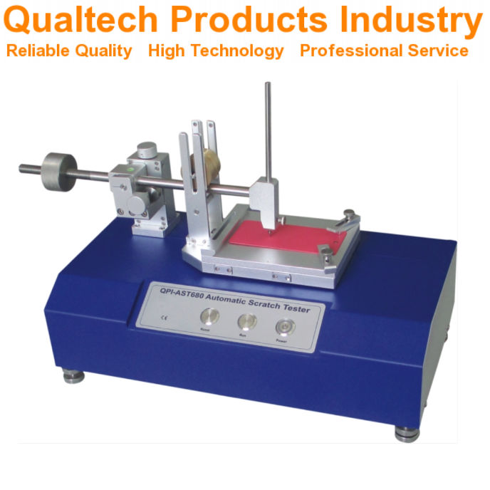
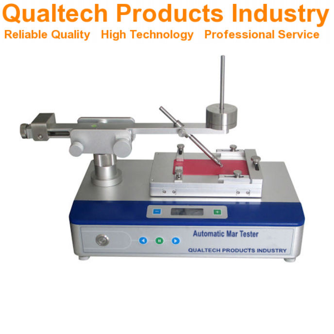
Scratch Test Equipment
The test requires a scratch tester apparatus that consists of a hemispherical-tipped stylus and a loading mechanism. According to ISO 1518-1, the stylus is typically made of hardened steel with a tip radius of 0.5 mm. The apparatus must be capable of moving the stylus across the coating at a constant speed.
The loading mechanism applies a defined, stable force perpendicular to the coating surface. You’ll need a device to measure this force accurately, usually in newtons.
The equipment should also include a means to secure the test panel firmly to prevent movement during testing. Some advanced models include optical systems to observe and record the scratch formation in real-time.
Test Parameters Setup
Before conducting the test, you must properly configure several key parameters. The applied load is critical and can be adjusted incrementally to determine the threshold at which coating failure occurs.
The test speed must be kept constant, typically between 30 mm/s to 40 mm/s. This ensures consistent results across different test sessions.
Temperature and humidity conditions should be standardized, usually at 23°C ± 2°C and 50% ± 5% relative humidity unless otherwise specified.
Your test panels must be prepared according to specific requirements with uniform coating thickness. The surface should be clean and free of contaminants.
Rest time between coating application and testing is also important, typically minimum 7 days for air-drying paints or as specified in the product data sheet.
Voorbereiding van testpanelen

Proper test panel preparation is crucial for accurate ISO 1518 scratch resistance testing. You must select panels that match your real-world application requirements.
For standard testing, use flat metal panels made of steel, aluminum, or tin plate. These panels should be clean and free from any defects that might affect test results.
Before coating application, you must clean the panels thoroughly to remove grease, dust, and other contaminants. Wipe the surface with a suitable solvent like acetone or isopropyl alcohol, then allow it to dry completely.
Apply the coating (paint or varnish) to the test panel according to the manufacturer’s instructions. This includes following recommended application methods, thickness, and drying conditions.
Important panel specifications:
- Size: Typically 150 mm × 100 mm
- Thickness: Minimum 0.8 mm for metal panels
- Flatness: Panels must be flat without warping
The coating should be applied evenly across the entire panel. You may need to measure the dry film thickness to ensure uniformity using a suitable measurement device.
Allow the coated panels to dry and cure completely according to the test method specifications. This typically includes:
- Drying at room temperature (23 ± 2)°C
- Relative humidity (50 ± 5)%
- Minimum curing time of 7 days (unless otherwise specified)
Before testing, condition the panels at the standard testing temperature and humidity for at least 16 hours.
Performing the Scratch Test

The scratch test requires careful execution to obtain reliable results. Proper technique and control of variables ensure consistent measurements of coating resistance to mechanical damage.
Applying the Scratch
To perform the scratch test according to ISO 1518, you must first secure your test panel firmly on a stable surface. The stylus tip should be positioned at one end of the intended scratch path.
Apply the predetermined constant load to the stylus. For the constant loading method described in ISO 1518-1, you need to select the appropriate weight based on coating type and expected performance.
Move the stylus across the coating at a steady speed of 30-40 mm/s. Maintain consistent pressure and angle throughout the test. The scratch should be approximately 10 cm long.
After completing the scratch, examine the resulting mark under good lighting conditions. Look for coating penetration down to the substrate, which indicates failure at that load level.
Control of Test Variables
Temperature and humidity significantly affect test results. You should conduct tests at 23 ± 2°C and 50 ± 5% relative humidity unless otherwise specified for specific coating types.
De test apparatus must be calibrated regularly to ensure accurate loading. Check the stylus tip condition before each test session—damaged or worn tips can invalidate results.
Substrate preparation and coating application must be standardized. Record film thickness at multiple points across the test panel.
Key variables to control:
- Speed of stylus movement
- Applied load precision (±0.1N)
- Stylus tip geometry (1 mm hemispherical)
- Panel temperature
- Coating age (fully cured)
Evaluation of Scratch Resistance


After conducting the ISO 1518 scratch test, proper evaluation of the results is crucial for determining coating performance. The assessment involves both qualitative visual inspection and quantitative measurement techniques.
Visual Inspection Criteria
The visual inspection of scratch resistance follows specific criteria outlined in the ISO 1518 standard. You should examine the tested surface under good lighting conditions, preferably using a light source at 45° to the surface.
Look for the following key indicators:
- First visible scratch mark: The lowest load at which a continuous scratch becomes visible
- Penetration to substrate: The load at which the coating is penetrated to reveal the substrate
- Coating deformation: Any signs of cracking, flaking, or delamination
You must record the results in newtons (N) to the nearest 0.1 N. For multi-coat systems, note which layer has been exposed by the scratch.
Take photographs of the scratch patterns for documentation purposes if required by testing protocols.
Measurement of Scratch Width
The scratch width measurement provides quantitative data for comparing different coating formulations. You can measure scratch width using:
- Optical microscope: With calibrated reticle or digital measuring capability
- profielmeter: For precise depth and width measurements
- Image analysis software: For automated measurement of scratch dimensions
Record measurements at several points along the scratch length, typically at 5 mm intervals. The standard testing procedure requires a minimum of five measurements to calculate an average width.
Express results in micrometers (μm) with appropriate precision. Higher quality coatings typically show narrower scratch widths at equivalent loads. Plot the scratch width against applied load to create a performance curve for comparative analysis.
Reporting Test Results

Accurate documentation of scratch resistance testing results is essential for quality control and product development. Proper reporting allows for meaningful comparisons between different coating formulations and helps determine if products meet required specifications.
Data Representation
When reporting ISO 1518 scratch test results, you should include both numerical and visual documentation. Record the critical load at which coating failure occurs in Newtons (N) for constant load tests according to ISO 1518-1. For variable load tests, document the minimum load that causes coating penetration.
Include photographs of the scratch patterns when possible. These provide visual evidence of the failure mode and help with future reference.
Create a standardized table format that includes:
- Sample identification
- Test date
- Applied load(s)
- Number of test repeats
- Mean critical load value
- Standard deviation
Each test report should clearly indicate which part of ISO 1518 was used (Part 1 or Part 2) as the test methodologies differ significantly.
Interpretation Guidelines
You should establish clear pass/fail criteria before conducting tests. Define the minimum acceptable scratch resistance value based on product specifications or industry standards.
When interpreting results, consider the following factors:
- Failure mode: Distinguish between complete penetration to substrate versus surface deformation
- Pattern consistency: Evaluate if failures occur uniformly or at random points
- Comparative analysis: Compare results against reference materials or previous batches
Note that higher critical load values indicate better scratch resistance. However, interpret results in context of the coating’s intended application environment.
Be careful not to overinterpret minor variations between samples. Statistical significance should be established before concluding meaningful differences exist. Consider environmental factors like temperature and humidity which may influence test outcomes.
Quality Control and Reproducibility

Ensuring reliable test results with the ISO 1518 scratch test requires strict quality control measures. This qualification is essential for industries where coating durability directly impacts product performance.
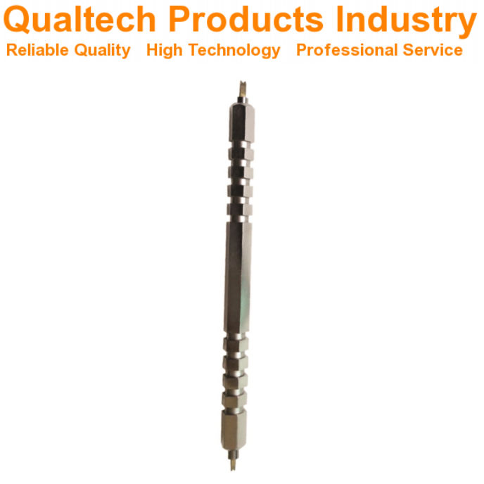
To maintain reproducibility, you must regularly calibrate your testing equipment. The scratching tool, particularly the hemispherically tipped needle mentioned in ISO 1518, requires inspection for wear or damage before each test session.
Environmental conditions play a crucial role in test consistency. You should conduct tests at standard temperature (23 ± 2°C) and relative humidity (50 ± 5%) unless otherwise specified.
Key Quality Control Factors:
- Equipment calibration
- Needle condition verification
- Consistent sample preparation
- Standardized environmental conditions
- Trained operators
Sample preparation techniques must follow the guidelines outlined in ISO 1518-1:2019. This includes proper curing time and uniform application thickness.
Test operators should receive thorough training on both equipment operation and result interpretation. Your interpretation criteria must be consistent across all testing personnel.
For multi-lab testing scenarios, round-robin testing helps verify consistency. You should establish acceptable variance ranges for your specific testing application.
Documentation is essential for quality assurance. Your records should include all test parameters, environmental conditions, and detailed observations of coating behavior during testing.
Maintenance and Calibration of Equipment

Proper maintenance and regular calibration of scratch test equipment ensure accurate and repeatable results when testing paint and varnish surfaces according to ISO 1518 standards. These practices are essential for maintaining the integrity of test data over time.
Routine Maintenance
Clean the scratch tool tip after each test to prevent cross-contamination between samples. Inspect the hemispherical tip regularly under magnification for signs of wear, deformation, or damage that could affect test results.
Replace the needle tip when any flattening or irregularities are observed, as this will compromise the validity of your scratch resistance measurements. Most manufacturers recommend tip replacement after approximately 100 tests.
Store the scratch tester in a dust-free environment and cover when not in use. Regularly check moving parts and loading mechanisms for smooth operation, applying appropriate lubricant as specified by the equipment manufacturer.
Wipe down guide rails and load-bearing surfaces monthly with a lint-free cloth. Examine the base plate for flatness and clean test surfaces thoroughly before mounting specimens to ensure proper contact.
Calibration Procedures
Calibrate your scratch tester at least every six months or after 500 tests, whichever comes first. Use certified reference materials with known scratch resistance values to verify equipment performance.
The load application system must be calibrated using certified weights traceable to national standards. Check that the applied force matches the displayed or set values within ±2% across the full range of test loads.
Calibration Check Points:
- Zero point verification
- Linear response across load range
- Speed control accuracy (5 mm/s ±0.5 mm/s)
- Horizontal movement stability
Maintain a calibration log documenting dates, procedures, results, and any adjustments made. When calibrating the scratch tip geometry, use a calibrated microscope to verify the 1 mm diameter hemispherical shape as specified in ISO 1518-1.
Record ambient conditions during calibration, as temperature and humidity can influence test performance. If your equipment fails calibration checks, contact the manufacturer for service before conducting further tests.
Safety Considerations

When performing the ISO 1518 scratch test for paints and varnishes, you should always prioritize safety. The test involves sharp instruments that could cause injury if mishandled.
Always wear appropriate personal protective equipment (PPE) during testing. This includes safety glasses to protect your eyes and gloves to protect your hands from sharp tools and chemicals.
The test may involve working with paints and varnishes that contain volatile organic compounds (VOCs). Ensure your testing area is well-ventilated to prevent inhalation of potentially harmful fumes.
Keep your workspace clean and organized. This reduces the risk of accidents and ensures accurate test results. Store all testing equipment properly when not in use.
Essential Safety Equipment:
- Safety glasses
- Protective gloves
- Lab coat
- Proper ventilation system
Be aware of the physical hazards associated with the testing apparatus. The scratch testing needles have sharp tips that can cause puncture wounds if mishandled.
When disposing of test samples and materials, follow local regulations for chemical waste disposal. Some coating materials may be classified as hazardous waste.
If you’re operating automated scratch testing equipment, ensure you’re familiar with the manufacturer’s safety instructions before use. Never bypass safety features on testing equipment.
Document any safety incidents during testing and review procedures regularly to prevent future occurrences. Your safety should always be the primary concern when conducting any laboratory testing.
Frequently Asked Questions

The ISO 1518 scratch test method includes specific parameters for measuring coating durability and resistance to mechanical damage. These common questions address testing equipment, applicable coatings, and result interpretation.
What types of coatings can be evaluated using the ISO 1518 scratch test method?
The ISO 1518 scratch test method can evaluate a wide range of coating materials. This includes single coatings or multi-coat systems of paint, varnish or related products.
You can test both decorative and protective coatings on various substrates. The method works well for automotive finishes, industrial coatings, and architectural paints.
What apparatus is required to conduct the scratch resistance test as per ISO 1518 standards?
The primary instrument needed is a scratch tester with a hemispherically tipped needle. This device must allow controlled application of force during the scratching process.
You’ll also need proper sample preparation tools and a means to measure the applied load. Some versions require a constant-load apparatus while others use a progressively increasing load mechanism.
How does the ISO 1518 method measure the scratch resistance of paints and varnishes?
The ISO 1518 method measures scratch resistance by drawing a hemispherically tipped needle across a coated surface under defined conditions. The test evaluates how well the coating withstands this mechanical stress.
You can observe at what load the coating begins to show damage. The higher the load required to produce visible damage, the better the scratch resistance of the coating.
What are the differences between ISO 1518-1 and ISO 1518-2 standards regarding scratch resistance testing?
ISO 1518-1 uses a constant load method where a specific weight is applied throughout the test. This provides a straightforward pass/fail assessment at predetermined loads.
ISO 1518-2 employs a variable load technique where force increases progressively during the test. This allows you to determine the exact load at which coating failure occurs.
How are scratch resistance test results interpreted under ISO 1518 guidelines?
Results interpretation depends on whether you’re using the constant load (ISO 1518-1) or variable load (ISO 1518-2) method. For constant load tests, you report whether the coating showed damage at each tested load.
For variable load tests, you record the minimum load that caused coating penetration. Higher numerical values indicate better scratch resistance properties.
Can ISO 1518 scratch test method be applied to both water-based and solvent-based coatings?
Yes, the ISO 1518 scratch test method works equally well for water-based and solvent-based coating systems. The test evaluates physical resistance properties regardless of the coating chemistry.
You can compare different coating technologies using this standardized approach. This makes it valuable for product development and quality control across various coating formulations.
- Gepubliceerd in Wetenschap & Onderzoek
ASTM D823 Standaardprocedures voor het produceren van films met een uniforme dikte van verflagen en gerelateerde producten op testpanelen
Het toepassen van de juiste dikte bij het aanbrengen van verf en coatings is van cruciaal belang voor een goede test- en kwaliteitscontrole. ASTM D823-18 biedt vijf gestandaardiseerde procedures voor het maken van uniforme verflagen op testpanelen, zodat u consistente en betrouwbare resultaten behaalt bij het aanbrengen van coatings.

Deze norm, voor het eerst vastgesteld in 1945 en bijgewerkt in 2022, valt onder toezicht van het ASTM-comité D01 voor verf en aanverwante coatings. Het biedt u specifieke methoden om testpanelen te vervaardigen die voldoen aan de industriële eisen voor dikte-uniformiteit.
U vindt gedetailleerde richtlijnen voor het aanbrengen van coatings op testpanelen, essentieel voor nauwkeurige prestatietests en kwaliteitsbeoordeling van verven en vergelijkbare producten. Deze procedures zorgen ervoor dat uw testresultaten betrouwbaar en vergelijkbaar zijn in verschillende testscenario's.
Belangrijkste punten
- De norm beschrijft vijf verschillende methoden voor het aanbrengen van uniforme verflagen op testpanelen
- Uw testresultaten worden betrouwbaarder wanneer u deze gestandaardiseerde toepassingspraktijken volgt
- Uniformiteit van de verfdikte heeft direct invloed op de nauwkeurigheid van prestatietests en kwaliteitscontrole
Toepassingsgebied van ASTM D823-18

ASTM D823-18 Biedt standaardprocedures voor het creëren van uniforme verf- en coatingfilms op testpanelen. Deze procedures helpen u consistente resultaten te behalen bij het testen van verfeigenschappen.
De norm behandelt drie hoofdmethoden voor het aanbrengen van coatings:
- Methode A:Handbediende film applicators
- Methode B: Mechanische filmapplicators
- Methode C: Spuitapplicatieapparatuur
U kunt deze werkwijzen gebruiken om testpanels voor te bereiden op de evaluatie verfkwaliteit, duurzaamheid en uiterlijkDe methoden werken met verf, vernis, lakken en aanverwante coatingmaterialen.
De norm valt onder ASTM-comité D01 over verf en aanverwante coatings, materialen en toepassingen. Subcommissie D01.23 over de fysische eigenschappen van aangebrachte verffilms beheert deze praktijken.
Deze werkwijzen helpen u bij het maken van testmonsters met een uniforme dikte. Deze uniformiteit is essentieel voor het nauwkeurig testen van de prestaties en eigenschappen van de coating.
Gerefereerde documenten

ASTM D823-18 vermeldt een aantal belangrijke normen en testmethoden ter ondersteuning van het correct meten van de filmdikte en het voorbereiden van panelen voor het testen van verf en coatings.
Gerefereerde normen
De testmethode voor het meten van de dikte van de droge film verwijst naar ASTM D1005, die micrometers gebruikt voor organische coatings.
U moet ASTM D609 volgen bij het voorbereiden van koudgewalste stalen panelen voor het testen van verf, lak en conversiecoatings.
Voor het meten van de natte filmdikte gebruikt u de ASTM D1212-testmethoden die speciaal zijn ontworpen voor organische coatings.
Deze normen zorgen samen voor consistente en nauwkeurige testprocedures. U moet de specifieke vereisten van elke norm waarnaar wordt verwezen, volgen om de juiste testomstandigheden te handhaven en betrouwbare resultaten te verkrijgen.
Vetgedrukte tekst geeft kritische normen aan:
- ASTM D609 – Voorbereiding van stalen panelen
- ASTM D1005 – Drogefilmmeting
- ASTM D1212 – Natte filmmeting
Terminologie

Belangrijke termen in ASTM D823 helpen verfproducenten en -technici bij het maken van uniforme testfilms met behulp van gestandaardiseerde applicatiemethoden en metingen.
Definities van termen die specifiek zijn voor deze standaard
Technieken voor het aanbrengen van verffilms erbij betrekken terugtrekkingwaarbij u met een mes of staaf verf over een oppervlak trekt om een gelijkmatige laagdikte te creëren.
Filmdikte Verwijst naar de gemeten diepte van de gedroogde coating op uw testpaneel. U moet een consistente dikte over het gehele paneeloppervlak handhaven.
EEN testpaneel is het voorbereide substraatmateriaal, zoals metaal of plastic, waarop u de coating aanbrengt voor evaluatie.
Uniforme film Dit betekent dat de coating gelijkmatig verdeeld is en een consistente dikte heeft, zonder dat er gebieden zijn die dikker of dunner zijn dan gespecificeerd. Deze uniformiteit is nodig om nauwkeurige testresultaten te verkrijgen.
Geautomatiseerde spuittoepassing gebruikt machinaal aangestuurde spuitapparatuur om coatings aan te brengen met nauwkeurige, herhaalbare instellingen voor druk, afstand en snelheid.
Betekenis en gebruik
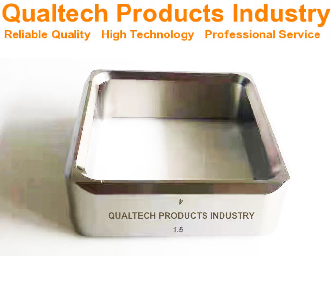

ASTM D823-praktijken Zijn essentieel bij het werken met coatings die bedoeld zijn voor spuittoepassingen in fabrieken of in het veld. Deze methoden helpen u consistente resultaten te behalen, of u nu binnen of buiten objecten coat.
Deze methoden zijn vooral belangrijk wanneer u metaalcoatings moet beoordelen op hun uiterlijk. Dit omvat het testen van eigenschappen zoals glans en kleurconsistentie over alle oppervlakken.
Wanneer u coatings aanbrengt met behulp van deze testmethoden, kunt u een lichte sinaasappelhuidtextuur of een spuitgolfpatroon waarnemen. Dit is normaal en komt overeen met wat u doorgaans ziet in praktijktoepassingen.
Deze gestandaardiseerde applicatiemethoden Zorg ervoor dat uw testresultaten betrouwbaar en herhaalbaar zijn. U kunt ze gebruiken om verschillende coatings te vergelijken of de prestaties van coatings onder verschillende omstandigheden te evalueren.
De vijf verschillende praktijken Geeft u flexibiliteit bij het kiezen van de meest geschikte methode voor uw specifieke coatingtype en testbehoeften. Elke stap helpt u bij het creëren van een uniforme filmdikte, wat cruciaal is voor nauwkeurige tests en evaluaties.
Inrichting
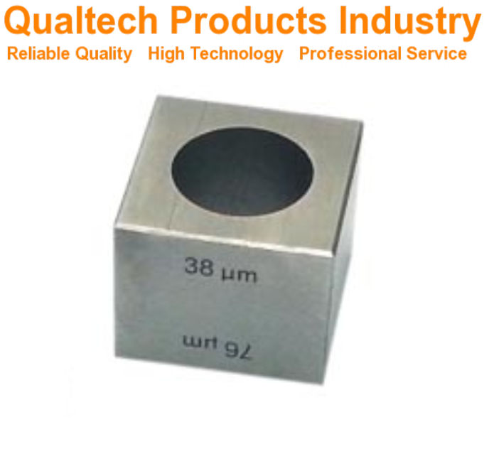

Geschikte apparatuur en gereedschappen zijn essentieel voor het produceren van uniforme verffilms en coatings op testpanelen. De specifieke eisen aan panelen, applicatiegereedschappen en testapparatuur garanderen consistente en betrouwbare resultaten.
Testpaneelspecificaties
Testpanelen moeten vlak, stijf en schoon zijn om een uniforme coatingdikte te bereiken. Gebruik panelen van staal, aluminium, glas of andere materialen. ASTM-goedgekeurde materialen.
De panelen hebben nauwkeurige afmetingen nodig met rechte randen en zonder oppervlaktedefecten. Standaard paneelafmetingen variëren van 3 x 6 inch tot 6 x 12 inch, afhankelijk van uw testvereisten.
Oppervlaktevoorbereiding is cruciaal. Reinig panelen grondig met oplosmiddelen om olie, stof en verontreinigingen te verwijderen voordat u de coating aanbrengt.
Hulpmiddelen voor het aanbrengen van films
Vijf belangrijkste toepassingsmethoden worden gebruikt voor het maken van uniforme films:
- Geautomatiseerde spuitmachines
- Motoraangedreven dipcoaters
- Motoraangedreven mesapplicators
- Handspuitpistolen
- Handmatige mesapplicators
Elk gereedschap moet vóór gebruik goed worden onderhouden en gekalibreerd. Geautomatiseerde apparatuur biedt een betere consistentie dan handmatige methoden.
Houd de sproeikoppen schoon en correct afgesteld. Vervang versleten bladen en applicators regelmatig.
Conditionerings- en testapparatuur
Uw testomgeving heeft gecontroleerde temperatuur- en vochtigheidsomstandigheden nodig. Gebruik gekalibreerde thermometers en hygrometers om de omgeving te controleren.
Standaardomstandigheden vereisen:
- Temperatuur: 23 ± 2°C
- Relatieve vochtigheid: 50 ± 5%
Laagdiktemeters en meetinstrumenten moeten correct gekalibreerd zijn. Bewaar de panelen horizontaal en stofvrij terwijl de folie uithardt.
Gebruik geschikte droogrekken die de natte film niet verstoren. Houd de uithardingstijden in de gaten volgens de coatingspecificaties.
Testmonsters
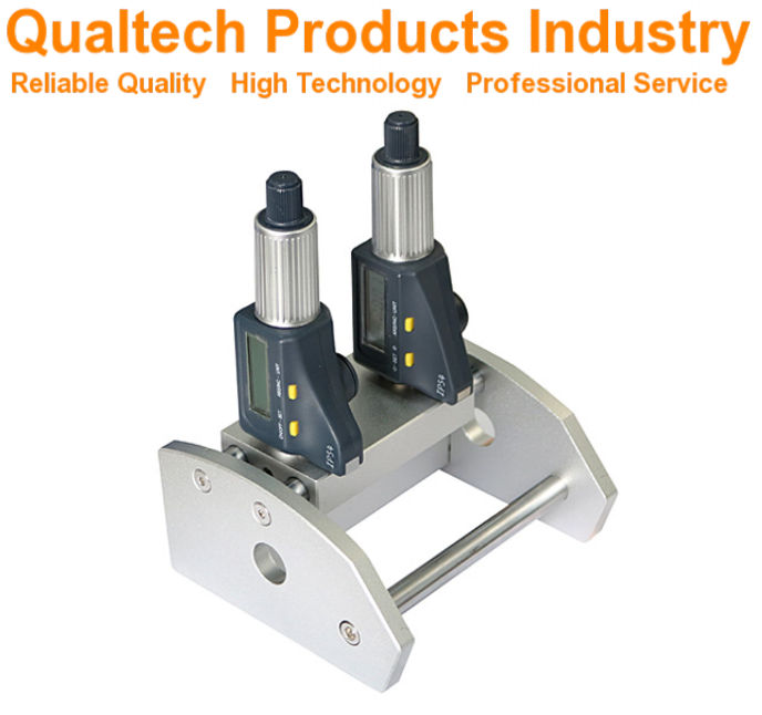

De juiste voorbereiding van het testpaneel en de juiste methoden voor het aanbrengen van de film zijn essentieel voor het behalen van nauwkeurige resultaten bij de beoordeling van de coating. Deze werkwijzen dragen bij aan consistente en betrouwbare tests van verven en coatings.
Voorbereiding van testpanelen
Testpanelen moeten schoon en vrij van verontreinigingen zijn voordat de coating wordt aangebracht. Selecteer panelen van metaal, glas, kunststof of hout op basis van uw testvereisten.
Reinig de panelen grondig met oplosmiddelen die geschikt zijn voor het substraatmateriaal. Gebruik voor metalen panelen terpentine of aceton om olie en resten te verwijderen.
Schuur het oppervlak indien nodig om de juiste ruwheid en hechting te verkrijgen. Veeg de panelen af met pluisvrije doeken om stof te verwijderen.
Richtlijnen voor paneelvoorbereiding Geef aan dat de temperatuur en vochtigheid tijdens de bereiding constant moeten blijven, doorgaans 23°C ± 2°C en 50% ± 5% relatieve vochtigheid.
Filmtoepassing:
Vijf gestandaardiseerde praktijken Er bestaan de volgende technieken voor het aanbrengen van uniforme coatingfilms: geautomatiseerde spuitmachines, motoraangedreven dompelcoaters, motoraangedreven mesmachines, handspuitpistolen en afstrijktechnieken.
Kies uw applicatiemethode op basis van het coatingtype en de gewenste filmdikte. Geautomatiseerde methoden bieden een betere herhaalbaarheid dan handmatige technieken.
Zorg voor de juiste toepassingsomstandigheden:
- Temperatuur: 23°C ± 2°C
- Relatieve vochtigheid: 50% ± 5%
- Luchtstroom: minimale trek
- Oppervlaktepositie: Horizontaal of verticaal zoals gespecificeerd
Laat de films onder gecontroleerde omstandigheden uitharden. Noteer de applicatiemethode, omstandigheden en uithardingstijd voor elk monster.
Procedure
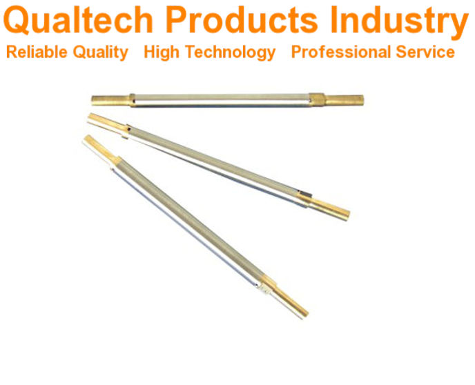

Het verfapplicatieproces vereist zorgvuldige controle van omstandigheden en technieken om hoogwaardige testresultaten te behalen. Het volgen van gestandaardiseerde methoden garandeert een consistente filmdikte en een goede coatingprestatie.
Omgevingsomstandigheden
U moet een specifieke temperatuur en luchtvochtigheid in uw testruimte aanhouden. Houd de kamertemperatuur tussen 23 °C ± 2 °C (73,4 °F ± 3,6 °F).
De relatieve luchtvochtigheid moet tussen 50% ± 5% liggen. Controleer deze voorwaarden Ten minste 24 uur voordat u met de aanvraagprocedure begint.
Registreer omgevingsmetingen aan het begin en einde van elke coatingsessie. Dit helpt bij het traceren van variaties die de filmvorming kunnen beïnvloeden.
Uniformiteit van de coating
Breng de coating aan met behulp van geautomatiseerde spuitapparatuur Voor de meest consistente resultaten: stel de spuitpistoolhouder zo in dat deze met een constante snelheid over het testpaneel beweegt.
Houd een constante afstand aan tussen de spuitmond en het testpaneeloppervlak. De typische afstand is 15-20 cm.
Controleer de laagdikte terwijl deze nat is met een nattelaagdiktemeter. Voer meerdere metingen uit over het paneeloppervlak.
Let op tekenen van:
- Sinaasappelschil textuur
- Loopt of zakt
- Ongelijke dekking
- Randopbouw
Drogen en uitharden
Plaats de gecoate panelen horizontaal tijdens de eerste droging. Dit voorkomt uitlopen en zorgt voor een gelijkmatige filmvorming.
Houd de panelen tijdens de eerste droogfasen uit de buurt van directe luchtstromen of warmtebronnen.
Volg de door de fabrikant aanbevolen uithardingstijden en -temperaturen. De meeste coatings hebben het volgende nodig:
- 24-48 uur bij kamertemperatuur
- OR 30-60 minutes at elevated temperatures (specified by coating type)
Test the hardness and adhesion only after full cure. Early testing can damage the coating film.
Report
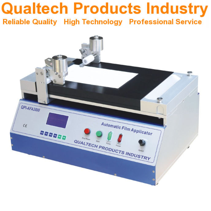

Proper reporting of test results from paint film thickness measurements ensures data accuracy and repeatability across different testing environments.
General Reporting Requirements
You must document all test conditions and methods used during the film thickness measurement process. Record the ambient temperature and relative humidity of the testing environment.
List all equipment used, including calibration dates and equipment identification numbers. Document any deviations from standard testing procedures.
Note the specific type and batch number of paint or coating tested. Include details about the test panel material, surface preparation methods, and application techniques used.
Test Results
Record film thickness measurements in micrometers or mils, taking multiple readings at specified points across the test panel surface. Include both individual measurements and calculated average values.
Note any defects, irregularities, or non-uniform areas observed in the coating film. Document visual observations of film quality, including surface texture and appearance.
Provide statistical analysis of measurement data when required, including standard deviation and variance. Include photographs or diagrams of measurement locations on test panels when needed for clarity.
Precision and Bias
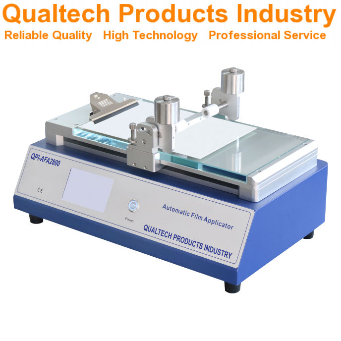

ASTM D823-18 does not include specific precision and bias data for the described practices. This is because the method focuses on preparation techniques rather than measurement results.
The precision of your film thickness will depend heavily on your equipment calibration and skill level. You need to maintain proper calibration of all measuring devices and applicators.
Regular verification of your test panels and application methods helps ensure consistent results. You should check your procedures against the ASTM D823 standard practices to maintain quality.
Common factors affecting precision include:
- Environmental conditions
- Application technique
- Equipment maintenance
- Panel preparation quality
- Film applicator condition
Your coating thickness measurements must be made according to appropriate ASTM standards for the specific type of coating being tested. This ensures your results can be compared with other labs following the same procedures.
When you report results, note any deviations from standard practices that might affect the uniformity of the film thickness. Keep detailed records of application conditions and methods.
Keywords

Paint films, coatings, test panels, film thickness, application methods, paint thickness testing, film uniformity.
ASTM D823-18 falls under the scope of ASTM Committee D01 on Paint and Related Coatings, Materials, and Applications.
The specific subcommittee responsible for this standard is D01.23 which focuses on Physical Properties of Applied Paint Films.
These standard practices were first established in 1945 and the current version was approved in 2022.
Key terms you’ll encounter in this standard include:
- Film application
- Coating thickness
- Test panel preparation
- Uniform film production
- Paint application methods
- Quality control testing
- Surface preparation
Frequently Asked Questions
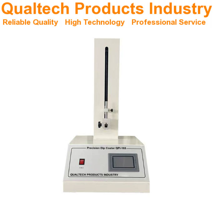

The ASTM D823-18 standard covers specific practices for creating uniform paint and coating films on test panels through multiple application methods. These practices address equipment requirements, process variables, safety protocols, and quality control measures.
What is the scope of ASTM D823-18 and what does it cover regarding film application?
Five distinct practices make up ASTM D823-18, each focused on producing uniform coating thickness on test panels. These practices include automated spray application, motor-driven dip coating, and other specialized methods.
The standard applies to paints, varnishes, and related coating materials used in testing and quality control applications.
Can you explain the methodologies outlined in ASTM D823-18 for achieving uniform thickness?
The standard specifies automated spray machines as one primary method for achieving consistent film thickness.
You must maintain precise control over application speed, distance, and material flow rate during the coating process.
Dip coating requires controlled immersion and withdrawal rates to ensure even coverage.
How does ASTM D823-18 differ from ASTM D3258 in terms of film application?
ASTM D823-18 focuses specifically on creating uniform thickness films for testing purposes. It emphasizes automated and mechanical application methods.
D3258 deals more broadly with paint film evaluation and includes different testing parameters.
What are the equipment requirements specified in ASTM D823-18 for preparing test panels?
You need calibrated automated spray equipment or dip coating machinery that can maintain consistent speeds and distances.
The test panels must meet specific cleanliness and surface preparation standards.
Your equipment must be able to control application parameters like pressure and flow rate precisely.
What variables should be controlled during the application process as per ASTM D823-18?
Temperature and humidity in your testing area need strict monitoring and control.
Material viscosity and application speed require consistent measurement and adjustment.
Distance between spray equipment and test panels must remain uniform throughout the process.
What are the safety considerations to keep in mind when following ASTM D823-18 practices?
You must use proper ventilation when working with paint and coating materials.
Personal protective equipment including respiratory protection, gloves, and eye protection is essential.
Keep all equipment properly grounded to prevent static electricity buildup.
- Gepubliceerd in Wetenschap & Onderzoek