
Normes d'essai ASTM
ASTM D3359: Standard Test Methods for Rating Adhesion by Tape Test – Essential Guide for Evaluating Coating Bond Strength in Materials Testing
Have you ever wondered how manufacturers test if paint or coatings will stick to a surface? ASTM D3359 is a standard test that helps answer this question. It uses simple tape to check how well coatings stick to materials like metal, plastic, or wood.

ASTM D3359 provides two methods to evaluate coating adhesion: the X-cut test et le cross-hatch test, both using pressure-sensitive tape to assess how well coatings remain attached to their substrates. These tests are crucial in industries such as automotive, aerospace, and construction where coating failures can lead to corrosion, product failure, or safety hazards. You can perform these tests in both laboratory and field settings, making them versatile for quality control.
The test works by cutting into the coating and applying tape over the cut area, then removing it quickly. How much coating comes off with the tape tells you about the adhesion quality. While simple to perform, proper technique is essential for reliable results, including using the right tape, making clean cuts, and removing the tape at the correct angle.
Points clés à retenir
- ASTM D3359 uses tape to test coating adhesion through either X-cut or cross-hatch methods, providing a simple yet effective quality control measure.
- The test applies to various industries including automotive, aerospace, and construction where coating durability directly impacts product performance and safety.
- Proper test technique including correct tape selection, clean cutting, and consistent tape removal angle is crucial for obtaining reliable and reproducible results.
Overview of ASTM D3359 and Its Purpose

ASTM D3359 is a standardized method for measuring how well coatings stick to surfaces using tape tests. This test helps determine coating quality and performance in various industries by providing simple, repeatable procedures for evaluating adhesion strength.
Definition and Scope of ASTM D3359
ASTM D3359 is a standard test method developed by the American Society for Testing and Materials for evaluating adhesion of coatings to substrates. The standard contains two distinct test methods: Method A uses an X-cut pattern, while Method B employs a cross-hatch pattern. These methods apply to most coating systems on various substrates, including metals, plastics, wood, and concrete.
The scope of ASTM D3359 covers coatings with thickness ranges from very thin films (less than 5 mils) to thicker applications. It’s particularly valuable for contrôle de qualité in manufacturing environments and field testing of applied coatings. The standard helps assess whether coatings will remain adhered during product use or environmental exposure.
What ASTM D3359 Is Designed to Evaluate
ASTM D3359 evaluates the adhesion strength of coatings to their substrate materials. The test specifically measures a coating’s resistance to separation from the substrate when force is applied using pressure-sensitive tape.
The test helps you determine:
- Coating adhesion quality
- Proper substrate preparation
- Coating application effectiveness
- Potential for coating delamination or failure
- Compatibility between coating systems and substrates
This method can identify adhesion problems resulting from improper surface preparation, contamination, incompatible primers, or coating formulation issues. You can use it for research and development, production quality control, or field evaluation of existing coatings.
General Principles Behind the Tape Test
The tape test operates on simple mechanical principles. First, you create deliberate cuts through the coating to the substrate, forming either an X-pattern or a grid. These cuts expose edges of the coating film that might be vulnerable to lifting.
Next, you apply standardized pressure-sensitive tape over the cut area and press it down firmly to ensure good contact. When you remove the tape at a specified angle and speed, it creates a pulling force on the coating edges.
The amount of coating removed by the tape indicates adhesion quality. Strong adhesion results in minimal coating removal, while poor adhesion causes significant coating detachment. You evaluate results using a standardized classification system that ranks adhesion quality from 5A (excellent) to 0A (very poor) for Method A, or 5B to 0B for Method B.
Specific Uses and Applications in Industry

The tape test method outlined in ASTM D3359 serves as a critical quality assessment tool across numerous manufacturing sectors. This straightforward yet effective test helps verify coating adhesion properties in real-world production environments.
Industries That Rely on ASTM D3359
The automotive industry extensively uses ASTM D3359 to evaluate paint and coating adhesion on vehicle components. Manufacturers test both exterior finishes and interior coatings to ensure durability under various conditions.
Aerospace companies apply this standard to verify protective coatings on aircraft parts will withstand extreme environmental conditions. The test helps ensure coating systems meet stringent safety requirements.
Electronics manufacturers utilize the tape test to check conformal coatings on circuit boards and electronic components. These coatings must remain firmly adhered to protect sensitive electronics from moisture and contamination.
The construction industry relies on ASTM D3359 to assess paints and coatings for architectural applications, including both interior and exterior building surfaces.
Importance of the Test for Quality Control
ASTM D3359 provides you with a quick, cost-effective way to detect potential adhesion problems before products reach customers. This early detection capability helps you avoid costly warranty claims and product recalls.
The test serves as a simple pass/fail assessment during production phases. You can easily incorporate it into your manufacturing process without disrupting workflow.
For your research and development teams, this test offers valuable feedback when formulating new coating systems. It helps identify which formulations perform best in real-world applications.
Quality control departments use the test to verify incoming raw materials meet specifications. This verification ensures consistency in your final products.
Example Applications for Different Materials
For metal substrates, you’ll find ASTM D3359 particularly useful in evaluating protective coatings on appliances, automotive parts, and industrial equipment. The test helps ensure coatings will withstand normal wear and environmental exposure.
When working with plastic components, the test helps you verify primer and topcoat adhesion on items like consumer electronics cases, automotive trim, and medical devices.
For wood products, ASTM D3359 helps you assess finish durability on furniture, flooring, and cabinetry. The test can identify potential issues with different wood species or surface preparations.
Glass and ceramic surfaces present unique coating challenges. You can use this test to evaluate specialized coatings on items like architectural glass, optical components, and ceramic tiles.
Types of Materials and Products Assessed

ASTM D3359 tape test evaluates adhesion performance across diverse materials and coating systems. This test method is especially valuable for determining coating adhesion on metal, plastic, wood, and composite materials.
Common Substrates and Coatings Evaluated
The tape test is widely used on metal substrates including steel, aluminum, copper, and zinc-coated surfaces. These metals often serve as base materials in automotive, aerospace, and construction industries.
Painted and powder-coated surfaces represent a primary application area. The test helps manufacturers verify proper adhesion of:
- Single-coat paint systems
- Multi-layer coating systems
- Powder coatings
- Industrial finishes
Plastic substrates such as polycarbonate, polyethylene, and ABS also benefit from adhesion testing. You’ll commonly see this test used for plastic components in consumer electronics, automotive parts, and medical devices.
Limitations Regarding Surface Types
Despite its versatility, ASTM D3359 has important limitations. The test is not suitable for very soft coatings like certain elastomers or highly flexible films, as they may deform during testing.
Textured or porous surfaces present challenges for accurate assessment. The tape may not make uniform contact with all surface areas, potentially yielding inconsistent results.
Very thin coatings (under 25 μm) may be difficult to evaluate with Method B (cross-cut test), while thick coatings (over 125 μm) often require alternative testing methods like ASTM D4541 pull-off test.
High-temperature resistant coatings sometimes show different adhesion properties at operating temperatures versus ambient testing conditions.
Test Performance and Interpretation

Performing the ASTM D3359 tape test correctly requires attention to detail and proper technique. The results provide valuable insights about coating adhesion when interpreted properly.
How the Adhesion Rating Is Determined
For Méthode A (X-cut test), ratings range from 5A to 0A. A rating of 5A means no peeling or removal of coating, indicating excellent adhesion. A 4A rating shows trace peeling along incisions, while 3A indicates jagged removal along incisions up to 1/16 inch (1.6 mm) on either side.
A 2A rating represents jagged removal along most of the incisions up to 1/8 inch (3.2 mm) on either side. A 1A rating shows removal from most of the area of the X under the tape. The lowest rating, 0A, indicates removal beyond the X area.
For Méthode B (cross-hatch test), ratings range from 5B (no detachment) to 0B (greater than 65% of the area removed). The assessment is made by comparing the cross-cut area to reference standards or descriptions in the test method.
Best Practices for Implementing the Tape Test
Always use specified tape with verified adhesion properties. Store tape properly and check its expiration date, as adhesive properties can change over time.
Clean the test surface thoroughly before testing. Avoid areas with obvious defects unless these are specifically being evaluated.
When making cuts, use a sharp tool and apply uniform pressure. For Method B, ensure the cuts penetrate through the coating to the substrate but don’t cut deeply into the substrate itself.
Apply tape at a consistent angle (approximately 180°) and smooth it with uniform pressure. Remove tape with a quick, steady pull at a 180° angle for consistent results.
Test multiple areas on a sample to account for variations in coating thickness or substrate properties.
Guidelines for Reliable Interpretation of Results
Document test conditions including temperature, humidity, and cure time of the coating. These factors can significantly impact adhesion performance.
Photograph test areas before and after tape removal for objective documentation and future reference.
When evaluating results, look beyond the numerical rating. Note the pattern of failure—whether it occurs at the coating-substrate interface or between coating layers.
Use consistent lighting when examining the test area. Angled lighting often reveals subtle coating removal that might be missed under direct lighting.
Remember that adhesion testing is comparative rather than absolute. Results should be interpreted against established specifications or control samples rather than as standalone values.
Implications and Significance of Test Results

The results from ASTM D3359 tape adhesion tests provide crucial insights that extend beyond simple pass/fail outcomes. These results directly impact product development decisions, quality control measures, and market acceptance.
Impact on Product Durability and Longevity
Poor adhesion test results often predict early coating failures in real-world applications. When your products show rating values of 0A-2A or 0B-2B, you can expect reduced service life and potential warranty claims from premature coating delamination.
Coatings that achieve 4B-5B or 4A-5A ratings typically deliver superior protection against corrosion, chemical exposure, and environmental stresses. This translates directly to extended maintenance intervals and lower lifecycle costs for your customers.
Test results also help identify weak points in your formulation or application process. For instance, consistent failures at substrate interfaces might indicate insufficient surface preparation, while cohesive failures within coating layers suggest formulation issues.
Role in Regulatory and Certification Processes
Many industry specifications establish minimum adhesion requirements based on ASTM D3359 results. In automotive manufacturing, OEM specifications typically require 4B or better adhesion for exterior finishes to ensure durability throughout the vehicle’s service life.
Building products often need to demonstrate specific adhesion ratings to obtain key certifications:
- AAMA 2605: Requires 5B rating for premium architectural coatings
- NFPA 130: Sets minimum adhesion standards for transit infrastructure
- IMO PSPC: Demands specific adhesion values for marine coatings
Your test results documentation becomes part of product validation packages required by regulatory bodies. Maintaining consistent adhesion testing records helps you demonstrate compliance during audits and can expedite approval processes for new markets or applications.
Comparing ASTM D3359 to Other Adhesion Test Methods

ASTM D3359 is one of several methods used to evaluate coating adhesion, but it has specific advantages and limitations compared to alternative testing approaches. Understanding these differences helps you select the most appropriate test for your specific application.
Key Differences from Cross-Cut and Pull-Off Tests
While ASTM D3359 is itself a cross-cut tape test, it differs from other adhesion tests in important ways. Unlike pull-off tests (ASTM D4541), which measure absolute adhesion strength in PSI, D3359 provides qualitative results on a 0-5 scale.
The tape test is less equipment-intensive than pull-off methods, requiring only a cutting tool, tape, and visual assessment. This makes it more accessible for field testing and quick evaluations.
Cross-hatch tests (ISO 2409) are similar to D3359 but use different rating scales and tape requirements. The spacing between cuts also varies based on coating thickness in both standards.
D3359 is less destructive than scribe tests (ASTM D1654), which evaluate corrosion resistance along with adhesion by exposing a deep scribe to corrosive environments.
When to Select ASTM D3359 Over Alternative Methods
Choose ASTM D3359 when you need a quick, portable assessment of coating adhesion. It’s ideal for field inspections and quality control checks where specialized equipment isn’t available.
This method works best for coatings under 5 mils (125 μm) thick on rigid substrates. For thicker coatings or flexible substrates, consider ASTM D4541 pull-off tests instead.
D3359 is particularly valuable for:
- Production line quality control
- Evaluating surface preparation effectiveness
- Comparing different coating formulations
- Troubleshooting adhesion failures
When quantitative measurements are required for engineering specifications, pull-off tests provide numerical data rather than the qualitative assessments from tape tests.
For coatings on concrete or other porous substrates, the pull-off method (ASTM D7234) typically offers more reliable results than the tape test.
Recent Developments and Evolving Best Practices

La adhesion testing landscape has evolved significantly with new technologies and industry demands shaping how ASTM D3359 tape tests are implemented and interpreted.
Advancements in Coating Technology and Testing
Digital imaging analysis has revolutionized how tape test results are documented and evaluated. Instead of subjective visual assessments, you can now use specialized software to quantify adhesion loss with greater precision. This reduces operator bias and improves test repeatability.
Automated tape application devices have emerged to standardize the pressure applied during testing. These devices ensure consistent 180° peel angles and uniform application force, addressing one of the main variables that previously affected test reliability.
Modified tape formulations specifically designed for adhesion testing now provide more consistent results across different environmental conditions. You’ll find specialized tapes with calibrated adhesion levels tailored for specific coating types that weren’t available five years ago.
Emerging Trends in Industrial Adhesion Evaluation
Cross-industry standardization efforts have led to more uniform implementation protocols. You can now reference comprehensive application guides that harmonize ASTM D3359 with ISO and other international standards.
Remote testing capabilities allow field technicians to conduct tests and share results in real-time with experts. Using mobile applications, you can document, analyze, and transmit adhesion test data to central databases for immediate evaluation.
AI-assisted interpretation tools are beginning to appear in quality control environments. These systems can recognize patterns in adhesion failures that might not be obvious to human inspectors and can link results to specific manufacturing variables.
Environmental considerations have prompted new guidelines for testing in extreme conditions. You’ll find updated protocols for high-humidity environments and temperature-variant testing scenarios not previously addressed in older versions of the standard.
Questions fréquemment posées
The ASTM D3359 tape test provides a standardized method for evaluating coating adhesion through simple yet effective procedures. This method helps quality control professionals assess material performance across various industries.
What is ASTM D3359 and what type of adhesion does it assess in materials?
ASTM D3359 is a standard test method that evaluates the adhesion of coating films to substrate materials. The test specifically assesses a coating’s resistance to separation from the substrate when force is applied using pressure-sensitive tape.
This method examines the bond strength between the coating and the underlying material. It determines whether the adhesion meets specified requirements for the intended application.
The test provides a qualitative assessment rather than a precise measurement of adhesion force. Results are rated on a scale from 0B to 5B (for the crosscut method) or 0A to 5A (for the X-cut method), with higher numbers indicating better adhesion.
Can you explain the procedural steps involved in executing the ASTM D3359 tape test?
The ASTM D3359 test can be performed using either Method A (X-cut) or Method B (crosshatch). For Method A, you make an X-cut in the coating, apply and remove tape, then evaluate the amount of coating removed.
Method B involves creating a lattice pattern of cuts, brushing away debris, applying tape over the grid, removing it at a specific angle, and examining the resulting pattern. The grid consists of either 6×6 or 11×11 cuts depending on coating thickness.
You must use specified tools including a cutting tool with the correct spacing, standard pressure-sensitive tape, a rubber eraser, and proper lighting for inspection. Precise technique is critical for accurate and reproducible results.
Why is the ASTM D3359 tape test significant within various industries and what are its primary applications?
The ASTM D3359 test is significant because it provides a standardized, relatively inexpensive method to assess coating adhesion without specialized equipment. This makes it accessible for field testing and quality control.
In manufacturing, the test helps determine if coatings will withstand normal use conditions. Poor adhesion can lead to coating failure, corrosion, and product degradation, making this test crucial for predicting product performance.
Industries like automotive, aerospace, construction, and electronics rely on this test to verify coating integrity on metal parts, architectural finishes, electronic components, and consumer goods. It helps ensure regulatory compliance and product durability.
Which materials or product categories typically undergo the ASTM D3359 tape test, and how is it relevant to them?
Painted metal components in automotive and aerospace applications commonly undergo ASTM D3359 testing. These industries require coatings that maintain integrity under extreme conditions and mechanical stress.
Architectural coatings on both metal and non-metal substrates are frequently tested using this method. Building materials must withstand weathering and environmental exposure without coating delamination.
Consumer electronics, appliances, and industrial equipment with protective or decorative coatings also benefit from this testing. The method helps manufacturers verify that their coatings will remain intact during normal product use.
Could you elucidate on the fundamental principles that the ASTM D3359 tape test is based upon?
The ASTM D3359 test is based on the principle that weak adhesion between a coating and substrate will fail when subjected to mechanical stress. The test creates controlled damage and then applies a standardized pulling force.
The test evaluates the interfacial bond strength rather than the cohesive strength within the coating itself. When tape is applied and removed, it creates a tensile force perpendicular to the substrate surface.
Adhesion failure can occur at different interfaces: between the coating and substrate (adhesive failure) or within the coating layers (cohesive failure). The test helps identify these different failure modes through visual inspection.
How should one interpret the results of the ASTM D3359 test, and what are the best practices in its implementation?
Interpret results using the standardized classification system: 5B/5A indicates no peeling, while 0B/0A shows removal of more than 65% of the coating. A rating of 4B or higher is generally considered acceptable for most applications.
Document results with photographs when possible to provide objective evidence of the test outcome. Note any unusual patterns or inconsistencies that might indicate specific adhesion problems.
For best practices, ensure proper sample preparation with clean, dry surfaces at recommended temperature and humidity. Use fresh tape for each test, apply consistent pressure, and remove tape at the specified angle and rate.
- Published in Normes d'essai ASTM, Science and Research
ASTM D6393/D6393M-21 Standard Test Method for Bulk Solids Characterization by Carr Indices: Essential Applications for Powder Flow Analysis in Industrial Processing
When working with bulk solids in industries like pharmaceuticals, food processing, or mining, understanding how powders and granular materials will behave during handling is crucial. ASTM D6393/D6393M-21 provides a standardized method for measuring the flowability and floodability characteristics of bulk solids through what are known as Carr Indices. These indices help you predict how materials will perform in real-world processing situations like storage, transportation, and manufacturing.

The Carr Indices test method evaluates several key properties including angle of repose, compressibility, angle of spatula, and cohesion. By measuring these properties, you can determine if your powder will flow smoothly through processing equipment or if it might cause problems like bridging in hoppers or inconsistent filling in packaging operations. This information is particularly valuable when selecting equipment, designing storage systems, or troubleshooting flow problems in existing operations.
Unlike single-parameter tests, the Carr Indices provide a comprehensive profile of material behavior. You can use these results to compare different materials, evaluate the effects of moisture or particle size on flowability, or determine if flow aids might be necessary. When properly implemented, this test method helps reduce production downtime, improve product consistency, and optimize bulk material handling processes across numerous industries.
Points clés à retenir
- ASTM D6393/D6393M-21 measures both flowability and floodability characteristics of powders and granular materials through standardized Carr Indices.
- The test results help predict bulk solid behavior during industrial processes, enabling better equipment selection and process design.
- Companies can reduce production problems and improve consistency by understanding the comprehensive material profile provided by the Carr Indices.
Purpose and Scope of ASTM D6393/D6393M-21

The ASTM D6393/D6393M-21 standard provides a framework for measuring and classifying powder and granular materials through Carr Indices. This test method helps understand how bulk solids behave during handling, storage, and processing operations.
Objective of Bulk Solids Characterization
The primary goal of this standard is to measure specific properties of powders and granular materials that affect their handling behavior. These measurements, known as Carr Indices, help you predict how materials will flow, pack, and behave during industrial processes.
The test applies to free-flowing and moderately cohesive materials up to 2.0 mm in size. Your material must be able to pour through a 6.0 to 8.0-mm diameter funnel when aerated.
By using this standard, you can:
- Quantify flow characteristics
- Measure packing properties
- Assess material uniformity
- Determine cohesiveness
These measurements provide objective data for comparing different materials or batches of the same material.
Industries Benefiting from the Standard
The D6393/D6393M-21 standard serves multiple industries that handle bulk solids regularly:
Pharmaceutical: You can use Carr Indices to ensure consistent powder blending and tablet production. This helps maintain quality in drug manufacturing.
Food Processing: When working with ingredients like flour, sugar, and spices, this test helps predict how they’ll behave during mixing and packaging.
Chemical Manufacturing: The standard helps you select appropriate equipment for handling specific materials and troubleshoot flow problems.
Mining and Minerals: You can use these tests to characterize ore concentrates and mineral powders before processing.
Ceramics and Building Materials: The test helps predict how cement, clay, and other materials will perform during production.
Overview of the Test’s Intended Applications
This standard test method serves several practical applications in bulk material handling:
You can use the Carr Indices to compare materials and establish specifications for purchasing or quality control. This helps ensure consistency in your production processes.
When designing handling equipment like bins, hoppers, and conveying systems, these measurements provide critical data. This helps you avoid costly flow problems and equipment failures.
The test also helps in troubleshooting existing problems with material flow or segregation. By measuring Carr Indices, you can identify which material properties are causing difficulties.
For research and development, the standard provides a consistent method to evaluate new formulations or processing techniques and their effects on material handling properties.
Significance and Benefits in Industry

Carr Indices provide essential metrics that help manufacturers and engineers understand powder behavior in industrial processes. These measurements directly impact product quality, equipment selection, and regulatory compliance across multiple industries.
Ensuring Product Quality and Consistency
Carr Indices help you maintain consistent product quality by providing quantifiable measurements of powder characteristics. When you understand how your materials flow and pack, you can predict final product uniformity.
Manufacturers in pharmaceuticals, food, and cosmetics rely on these measurements to ensure batch-to-batch consistency. For example, poor flowability identified through Carr testing might indicate potential tablet compression issues in pharmaceutical manufacturing.
Companies use these indices to set quality specifications for incoming raw materials. This allows you to reject unsuitable powders before they enter your production line.
The measurements also help you troubleshoot quality issues. If your finished product suddenly shows inconsistencies, Carr Index testing can identify if powder property changes are the root cause.
Impact on Material Handling and Processing
Carr Indices directly influence equipment selection and process design decisions in your facility. Understanding your material’s angle of repose helps you determine proper hopper angles to prevent flow stoppages.
Poor flow properties identified through testing signal the need for flow aids or specialized equipment. This knowledge prevents costly production interruptions and equipment damage.
Bulk density measurements from Carr testing help you:
- Calculate accurate storage requirements
- Design appropriate conveying systems
- Select correct feeder types
- Optimize mixing processes
When designing new processes, these indices allow you to anticipate handling challenges before committing to equipment purchases. This saves significant capital expenditure and prevents production delays.
Role in Regulatory Compliance
Regulatory agencies increasingly expect manufacturers to understand and control their materials’ physical properties. Carr Indices provide the documentation needed to demonstrate this understanding.
In pharmaceutical manufacturing, FDA guidelines require thorough material characterization. Carr testing fulfills this requirement by providing standardized measurements of powder properties that affect final product quality.
The repeatability of Carr testing makes it valuable for regulatory submissions. You can confidently provide consistent data that supports your manufacturing processes.
For companies with global operations, the international recognition of ASTM standards means Carr Indices testing satisfies regulatory requirements across different regions. This eliminates the need for redundant testing methodologies.
Types of Materials and Products Covered

The ASTM D6393/D6393M-21 test method is specifically designed for analyzing free-flowing and moderately cohesive materials with defined size parameters. This standardized approach helps characterize powders and granular materials across multiple industries.
Bulk Powdered Solids and Granules
The test method primarily covers particles up to 2.0 mm (approximately 1/16 inch) in size. Materials must be able to pour through measurement apparatus openings to be suitable for testing.
Free-flowing powders like talc, flour, and fine sand can be easily evaluated using this method. These materials move readily under gravity with minimal resistance.
Moderately cohesive powders that exhibit some particle-to-particle adhesion can also be tested. Examples include certain pharmaceutical powders, food ingredients, and fine chemical compounds.
The method is not suitable for highly cohesive materials that clump together or sticky substances that adhere to testing equipment. Very coarse materials exceeding the 2.0 mm size limit also fall outside the test’s scope.
Industries and Product Examples
Pharmaceutical industry: The test helps characterize excipients, active ingredients, and finished drug formulations. Understanding powder flow properties is crucial for tablet manufacturing and capsule filling operations.
Food processing: Ingredients like sugar, salt, spices, and baking additives benefit from Carr Indices testing to predict handling behavior during production.
Chemical manufacturing: Raw materials and finished products such as pigments, catalysts, and specialty chemicals can be evaluated for quality control.
Construction materials: Cement, fine aggregates, and additives used in concrete and mortar formulations fall within the test parameters.
Cosmetics industry: Powdered makeup products, talcum powder, and other fine cosmetic ingredients can be characterized using this method.
Principles of the Carr Indices Test Method

The Carr Indices test method evaluates the flow properties and behavior of powders and granular materials through a series of specific measurements. These indices provide valuable information about how bulk solids will perform during handling, storage, and processing.
Measured Properties and Their Relevance
The test method consists of eight distinct measurements and two calculations that characterize different aspects of bulk solid behavior. These include:
- Angle of repose: Indicates the material’s flowability
- Angle of fall: Measures stability after impact
- Angle of difference: Calculated as angle of repose minus angle of fall
- Loose bulk density: How the material packs under gravity alone
- Packed bulk density: How the material packs under applied force
- Compressibility: Calculated from the density measurements
These properties help you predict how a powder will behave during industrial processes. For example, high compressibility often indicates poor flow characteristics, while low angles of repose suggest free-flowing materials.
Concepts scientifiques sous-jacents
The Carr Indices are based on fundamental physical principles that govern particulate matter behavior. The test examines how particles interact with each other and their environment through:
- Interparticle forces: Measures cohesion between particles including van der Waals forces and electrostatic interactions
- Gravitational effects: How particles settle and arrange under gravity
- Frictional characteristics: Surface properties that affect flowability
The measurements capture both static and dynamic properties of bulk solids. By quantifying these behaviors, you can better understand how powders will perform in real-world applications such as hopper discharge, blending operations, or tablet compression.
Interpreting Test Results and Implications

The Carr Indices provide quantifiable data that helps predict how bulk materials will behave during handling, storage, and processing. Understanding these results properly is essential for making informed decisions about material selection and process design.
What Carr Indices Reveal About Material Performance
Carr Indices provide critical insights into material flow behavior. The angle of repose indicates how easily a material will flow under gravity – lower angles (below 30°) suggest excellent flowability, while higher angles (above 45°) indicate poor flow characteristics.
Compressibility values reveal how a material responds to pressure. Materials with low compressibility (below 15%) typically flow more freely than highly compressible materials (above 28%), which tend to be cohesive and prone to bridging in hoppers.
The uniformity ratio helps predict segregation potential. Values below 2 indicate uniform particle distribution, reducing segregation risks during transport and handling.
Dispersibility measurements show how easily materials aerate. High dispersibility values suggest materials may create dust issues or fluidize unexpectedly during processing.
Common Decision-Making Based on Test Outcomes
You can use Carr Indices to select appropriate handling equipment. For materials with poor flowability indices, you might choose vibrating feeders or air-assisted discharge systems rather than gravity-fed options.
Storage vessel design decisions often rely on these test results. Materials with high angles of repose and compressibility typically require steeper hopper angles and specialized discharge aids to prevent flow problems.
Blending operations benefit from uniformity data. When mixing components with significantly different Carr Indices, you may need to adjust blending parameters or equipment selection to achieve homogeneity.
Process troubleshooting becomes more effective with Carr data. If you experience flow problems, comparing current material properties with historical Carr Index benchmarks can identify when material changes are causing the issues.
Application Example: Case Study in Powder Processing

The Carr Indices test method provides valuable insights when applied to real industrial powder processing scenarios. This case study examines how a pharmaceutical company used ASTM D6393 to optimize their tablet manufacturing process.
Selection and Preparation of Representative Samples
The pharmaceutical manufacturer faced inconsistent tablet quality issues related to their calcium carbonate powder. They selected representative samples from three different suppliers for testing using the Carr Indices method.
Each 100g sample was carefully dried at 40°C for 24 hours to remove moisture that could affect flow properties. The samples were then conditioned at room temperature (23±2°C) and relative humidity (50±5%) for 12 hours before testing.
The company ensured proper sample splitting using a rotary sample divider to maintain representative properties. This careful preparation was crucial since variations in particle size, moisture content, or agglomeration would significantly affect the test results.
Real-World Use Scenario and Insights Gained
The pharmaceutical company performed complete Carr Indices testing on all three powder samples. Results showed significant differences in flowability and compressibility:
Supplier Comparison Results:
| Supplier | Flow Index | Pack Index | Flowability Rating |
|---|---|---|---|
| UN | 75 | 18 | Bien |
| B | 62 | 23 | Équitable |
| C | 83 | 14 | Excellent |
The tests revealed Supplier C’s powder had superior flow characteristics that reduced jamming in the tablet press. Additionally, its lower pack index indicated better volume consistency during filling operations.
Based on these findings, the company switched to Supplier C, resulting in a 15% reduction in tablet weight variation and 30% fewer production stoppages. This change saved approximately $45,000 annually in production costs while improving product quality.
Best Practices for Implementation and Result Interpretation

Proper implementation of ASTM D6393/D6393M-21 requires attention to detail in both testing procedures and data analysis. Following established protocols ensures reliable characterization of bulk solids through Carr Indices.
Maximizing Test Accuracy and Repeatability
Sample preparation is critical for reliable results. Ensure materials are properly dried and conditioned according to the standard before testing. Material should be at equilibrium with the testing environment.
Temperature and humidity must be controlled and documented. Test in an environment with 20-25°C and relative humidity below 65% for best results.
Calibrate all equipment regularly, including the angle of repose apparatus and density measuring devices. Document calibration dates and results.
When measuring angle of repose, pour material consistently at the same rate for each test. Variations in pouring technique can significantly affect results.
Perform at least three measurements for each index and calculate the average. This minimizes the impact of random variations.
For cohesive materials, ensure proper aeration before testing to prevent false readings due to agglomeration.
Effective Reporting and Communication of Results
Document all test conditions thoroughly, including:
- Material specifications (particle size, moisture content)
- Testing environment (temperature, humidity)
- Equipment used
- Any deviations from standard procedure
Present data in both tabular and graphical formats. Graphs help visualize relationships between different Carr Indices for easier interpretation.
Compare results to established benchmarks for similar materials. This provides context for interpretation of flowability and cohesion characteristics.
Include statistical analysis of repeated measurements. Report standard deviations to indicate result reliability.
When communicating results, highlight specific indices most relevant to the intended application. For example, emphasize angle of repose for hopper design or compressibility for tablet formulation.
Use standardized terminology from the ASTM standard when describing results to ensure clear communication across teams and organizations.
Comparison with Related Test Standards
When selecting a test method for bulk solid characterization, understanding how the Carr Indices method compares to alternatives helps you make informed decisions. Several other standardized tests measure similar properties but with different approaches and applications.
Key Differences from Alternative Methods
The Carr Indices method (ASTM D6393/D6393M-21) differs from the Jenike Shear Test (ASTM D6128) in fundamental ways. While Carr focuses on multiple flowability properties through various indices, Jenike specifically measures shear strength and wall friction for hopper design.
Carr Indices work best for free-flowing to moderately cohesive materials up to 2mm in size. In contrast, ASTM D6683 (Bulk Density Values of Powders) specifically measures density changes under compressive stress without addressing flow characteristics.
The Carr method provides a broader characterization profile with multiple measurements in one standard. This gives you a more comprehensive material assessment compared to single-property tests.
Choosing the Appropriate Test for Application Needs
Your application requirements should drive test selection. Choose Carr Indices when you need a comprehensive profile of material handling properties or when comparing different powder formulations.
Select the Jenike Shear Test when designing storage equipment like hoppers and silos. This test provides critical parameters for proper equipment sizing and design.
For applications focused solely on compressibility or bulk density changes under pressure, ASTM D6683 offers more specialized measurements.
Consider your material characteristics too. Very cohesive or larger particle materials (>2mm) might require alternative test methods as they fall outside Carr’s suitable range.
Questions fréquemment posées
The ASTM D6393/D6393M-21 test method provides crucial information about bulk solid properties through Carr Indices. These measurements help industries evaluate material flow characteristics, optimize processing conditions, and ensure product quality.
What is the significance of the ASTM D6393/D6393M-21 test method in the characterization of bulk solids?
The ASTM D6393/D6393M-21 test method is significant because it provides a standardized way to measure multiple properties of powders and granular materials. It helps you understand how materials will behave during handling, storage, and processing.
The test generates Carr Indices that quantify flow properties, compressibility, and other important characteristics. These measurements allow you to predict potential processing problems before they occur.
By using this standard, you can make informed decisions about equipment selection, process design, and quality control measures based on reliable data rather than guesswork.
How does the ASTM D6393/D6393M-21 contribute to quality control and assurance in the materials industry?
This test method establishes consistent quality benchmarks for raw materials and finished products. You can use it to verify that incoming materials meet your specifications before accepting shipments.
The Carr Indices provide quantitative data that helps you track material consistency over time. When deviations occur, you can quickly identify and address quality issues.
Many industries use these measurements as part of validation protocols for new suppliers or materials. The standardized nature of the test ensures reliable comparisons between different material batches or sources.
What types of materials are primarily tested using the ASTM D6393/D6393M-21 Standard Test Method, and why are they selected?
Pharmaceutical powders are commonly tested to ensure consistent tablet production and drug delivery. Food ingredients like flour, sugar, and powdered additives benefit from this testing to maintain product quality and manufacturing efficiency.
Chemical industry powders, pigments, and catalysts require flow property analysis to prevent processing issues. Mining and mineral processing operations use these tests to characterize ore concentrates and other processed materials.
These materials are selected for testing because their flow properties directly impact processing efficiency, product quality, and equipment performance. Materials with unpredictable flow behaviors can cause significant production problems.
Can you explain the fundamental principles that the ASTM D6393/D6393M-21 test is based on?
The test measures both static and dynamic properties of bulk solids through a series of measurements. It examines how particles interact with each other and with container surfaces.
Bulk density measurements compare loose and packed states to determine compressibility. Angle of repose and angle of fall tests evaluate how materials form piles and how stable those piles are.
The method also measures cohesion, uniformity, and dispersibility. These properties together form a comprehensive profile of how a material will behave during handling and processing operations.
What are the typical outcomes and implications of utilizing the ASTM D6393/D6393M-21 test method in material characterization?
Test results help you identify potential flow problems like bridging, ratholing, or segregation. You can use this information to modify formulations or processing parameters to improve material performance.
The data allows you to properly size hoppers, feeders, and other handling equipment. This prevents costly redesigns and production delays.
You can establish specification limits for critical material properties based on the Carr Indices. These specifications ensure consistent processing and final product quality across multiple production batches.
How does ASTM D6393/D6393M-21 differ from other bulk solids characterization methods, and why might it be preferred?
Unlike shear cell testing, which focuses primarily on cohesive strength, D6393 measures multiple properties in a single test sequence. This gives you a more complete picture of material behavior.
Compared to simple flow-through funnel tests, the Carr Indices provide quantitative measurements rather than just pass/fail results. This allows for more precise material specifications and troubleshooting.
The test equipment is relatively simple and standardized, making it accessible for many laboratories. Results are also highly reproducible when performed correctly, allowing reliable comparisons between different testing facilities.
- Published in Normes d'essai ASTM, Science and Research
ASTM C1444-00 Standard Test Method for Measuring the Angle of Repose of Free-Flowing Mold Powders: Applications and Industry Significance in Materials Testing
ASTM C1444-00 was a standard test method used to measure how easily mold powders flow by determining their angle of repose. Mold powders are materials used in steel production that help control heat transfer and protect molten steel. This test was particularly important for steel manufacturers because the flowability of mold powders directly impacts production quality and efficiency.

When mold powders don’t flow properly, they can cause defects in steel products and production delays. The angle of repose measurement provided a simple way to predict how a powder would behave during actual use. Though this standard was withdrawn in 2005, the principles behind it are still valuable for quality control in steel manufacturing today.
Points clés à retenir
- The angle of repose measurement indicates how easily mold powders will flow during steel production processes.
- Poor flowing mold powders can cause serious defects in the final steel products and production inefficiencies.
- While this specific standard has been withdrawn, its testing principles remain relevant for quality control in modern steel manufacturing.
Purpose and Specific Use of ASTM C1444-00

ASTM C1444-00 provides a standardized approach to measure how easily mold powders flow by determining their angle of repose. This test helps manufacturers evaluate powder quality and predict how powders will behave during industrial processes.
Objectives of the Test Method
The primary objective of ASTM C1444-00 is to determine the precise angle at which free-flowing mold powders begin to flow. This angle serves as a critical indicator of powder flowability. When powders exceed this specific angle, they will flow naturally under gravitational force.
The test aims to provide consistent, reliable measurements that can be reproduced across different testing facilities. By standardizing this measurement, manufacturers can compare different powder batches effectively.
Another key objective is to help predict how powders will behave during industrial applications. Understanding the angle of repose allows you to anticipate potential flow issues before they occur in production environments.
Measurement of Angle of Repose for Mold Powders
The angle of repose measurement indicates how powder particles interact with each other. It reveals important properties like cohesiveness, internal friction, and overall flow characteristics. The test specifically addresses free-flowing mold powders, which are common in metal casting operations.
Several factors affect this measurement, including:
- Particle size
- Particle shape
- Bulk density
These physical properties directly influence how easily powder flows down an inclined surface. Powders with smaller angles of repose typically flow more freely than those with larger angles.
The test provides values in both inch-pound units and degrees, with the degree measurement being the standard reference. This measurement helps you assess whether a specific powder batch will perform adequately in your production processes.
Scope Within Materials Testing
ASTM C1444-00 fits within the broader scope of powder characterization methods. It specifically addresses free-flowing mold powders used in metal casting applications, where powder flowability directly impacts production quality.
The test is particularly valuable for:
- Quality control in powder manufacturing
- Incoming material verification
- Process troubleshooting
- Product development
Unlike other flowability tests that might measure different properties, this method focuses specifically on the angle of repose—a fundamental property that correlates directly with practical flowability.
The standard complements other powder testing methods like bulk density measurements and sieve analysis. When used together, these tests provide a comprehensive picture of powder behavior that helps you optimize manufacturing processes and ensure consistent product quality.
Significance in Industrial Applications

The angle of repose measurement specified in ASTM C1444 plays a critical role in metallurgical industries and manufacturing processes that depend on powder flow characteristics. This test directly influences operational efficiency and final product quality.
Role in Metallurgical Processes
In continuous casting operations, mold powders with appropriate flow characteristics ensure proper distribution across the steel meniscus. When you select mold powders with optimal angle of repose values (typically 35-45 degrees), you achieve better lubrication between the solidifying shell and mold walls.
Powder flow behavior directly impacts heat transfer rates in the casting process. Well-flowing powders (indicated by lower repose angles) distribute more evenly, creating consistent thermal barriers that protect against defects.
The test helps you predict how powders will behave during automated feeding systems. Powders that test within specification limits reduce bridging issues in hoppers and ensure constant feed rates to the mold.
Impact on Production Quality and Consistency
When you maintain strict control over powder flowability through repose angle testing, you significantly reduce casting defects. Inconsistent powder flow leads to slag entrapment and surface irregularities in the final product.
The test enables you to establish quality control parameters for powder acceptance. By setting specific angle of repose limits (±2° tolerance is common), you can reject batches that may cause operational problems.
Production efficiency improves when powders maintain consistent flow properties. Testing helps you identify variations between batches that might otherwise cause unexpected downtime or quality fluctuations.
Regular testing according to C1444 provides data for trend analysis. This allows you to correlate angle of repose values with specific product quality metrics and optimize your powder selection process.
Types of Materials Evaluated

ASTM C1444-00 specifically addresses materials used in the metallurgical industry where powder flow characteristics are crucial for quality control and processing efficiency. This test method focuses on determining flow properties through angle of repose measurements.
Free-Flowing Mold Powders
Mold powders are specialized materials used in continuous casting of steel to protect the molten metal and control heat transfer. These powders typically contain:
- Fluxing agents (lime, silica)
- Deoxidizers
- Lubricants
- Carbon additives
The key characteristic of mold powders evaluated by ASTM C1444 is their ability to flow freely. This property ensures consistent delivery during the casting process.
Particle sizes generally range from 50 to 300 micrometers for optimal flowability. The shape of particles also affects flow characteristics, with more spherical particles typically flowing better than irregular ones.
The bulk density of these powders usually falls between 0.5 and 1.2 g/cm³, which influences how they behave during handling and application in casting operations.
Other Relevance to Industrial Powders
While developed for mold powders, the principles in ASTM C1444 can apply to other industrial powder materials with similar flow characteristics.
This includes:
- Metallurgical fluxes
- Refractory powders
- Ceramic raw materials
- Some chemical processing powders
The test method proves valuable for powders where controlled flow is critical to production quality. You can use angle of repose data to:
- Compare different powder formulations
- Predict handling behavior in hoppers and feeders
- Establish quality control specifications
Industries beyond steelmaking that benefit from this type of evaluation include powder metallurgy, ceramics manufacturing, and chemical processing. The fundamental principles apply whenever you need to assess the free-flowing nature of fine particulate materials.
Underlying Principles of the Test Method

The angle of repose test measures how freely powder materials flow, which directly relates to their handling properties in industrial applications. This fundamental property helps predict powder behavior during manufacturing processes.
Concept of Angle of Repose
The angle of repose represents the steepest angle at which a powder can be piled without flowing. When you pour powder onto a flat surface, it forms a conical pile. The angle between this pile’s slope and the horizontal plane is the angle of repose.
For mold powders tested under ASTM C1444, this angle indicates flowability characteristics. Lower angles (typically below 30°) suggest excellent flow properties. Higher angles (above 45°) indicate poor flowability.
The test works on the principle of gravitational forces competing with interparticle forces. When gravity overcomes the friction between particles, the powder flows. This balance point defines the characteristic angle for each powder.
Factors Influencing Powder Flowability
Several physical properties affect how mold powders flow during the angle of repose test:
- Particle size: Larger particles generally flow more freely than smaller ones
- Particle shape: Round particles flow better than irregular shapes
- Moisture content: Higher moisture typically reduces flowability
- Surface roughness: Smoother particles flow more easily
- Bulk density: Denser materials often demonstrate different flow patterns
Cohesive forces between powder particles create resistance to flow. These include van der Waals forces, electrostatic interactions, and liquid bridges from moisture. Environmental factors like humidity and temperature can significantly alter these properties.
The test accounts for these variables by using standardized equipment and procedures to ensure consistent measurements across different testing facilities.
Interpreting Test Outcomes

The angle of repose measurement provides critical data for material handling operations and helps predict powder behavior under various conditions. Understanding these test results properly can significantly improve manufacturing efficiency and product quality.
Implications for Process Control
The angle of repose directly impacts how you should design and operate powder handling equipment. Lower angles (below 30°) indicate excellent flowability, allowing for faster processing speeds and fewer flow aids in hoppers and chutes.
When test results show angles between 30-45°, you should consider implementing moderate flow assistance mechanisms. These powders may experience occasional bridging or rat-holing in storage containers.
For angles exceeding 45°, you must incorporate significant flow aids such as vibration, air assistance, or special hopper designs. These high angles signal potential processing challenges including inconsistent flow rates and unpredictable material discharge.
Regular testing helps you detect changes in powder properties before they cause production problems. This allows for proactive adjustments to processing parameters.
Significance of Angle of Repose Values
The specific angle value reveals important characteristics about your mold powder’s behavior. Angles below 25° indicate extremely free-flowing materials that may aerate easily or cause dusting issues during handling.
Angles between 25-30° represent optimal flow characteristics for most mold powder applications. These materials typically provide consistent performance in continuous casting operations.
Values between 30-40° suggest moderate cohesiveness. You should monitor these powders closely as environmental factors like humidity can push them into problematic flow regions.
Industry standards often specify acceptable angle ranges for specific applications. Deviations from these ranges may signal contamination, moisture absorption, or particle segregation issues that require immediate attention.
Examples of Practical Applications

ASTM C1444-00 test method finds its application in several industrial settings where the flow properties of mold powders affect manufacturing processes. The angle of repose measurement provides valuable data for both steelmaking operations and quality control protocols.
Assessment with Steelmaking Mold Powders
In continuous steel casting operations, mold powders must flow consistently into the mold to create uniform slag layers. The angle of repose test helps determine if a powder will flow properly during production conditions.
When testing new formulations, operators can quickly compare flow properties between different batches. A typical acceptable angle of repose for steelmaking mold powders ranges between 30-40 degrees.
Changes in measured angles can indicate potential problems with:
- Particle size distribution
- Moisture contamination
- Raw material variations
- Storage condition effects
You can use these measurements to troubleshoot production issues when slag formation appears inconsistent or when mold powder feeding systems experience blockages.
Relevance for Quality Assurance
Quality assurance departments rely on angle of repose testing as part of incoming material inspection protocols. This test serves as a quick screening method that requires minimal equipment and training.
When you establish specification limits for acceptable angles, you create an objective acceptance criterion for powder shipments. Many steel producers maintain databases of historical measurements to identify trends in supplier quality.
The test results can be correlated with:
- Casting performance metrics
- Defect rates
- Production speeds
- Other powder properties
You can integrate this test into a comprehensive quality management system alongside chemical composition testing and particle size analysis. This combination provides better predictive capability for powder performance during actual casting operations.
Best Practices for Test Implementation

Implementing ASTM C1444 correctly requires attention to detail and consistency. The following practices help ensure reliable results when measuring the angle of repose for free-flowing mold powders.
Ensuring Accurate and Representative Results
Always conduct tests in a controlled environment with stable temperature and humidity. These variables can significantly affect powder flowability.
Use a clean, dry funnel with consistent dimensions as specified in the standard. Any residue or moisture can alter flow characteristics.
Perform at least three measurements per sample and calculate the average angle. This helps minimize random errors and provides more reliable data.
Maintain a consistent drop height during testing. Variations in height can change the powder pile formation and affect your angle measurements.
Key point: Record both the angle and the powder behavior during testing. Note any irregular flow patterns that might indicate quality issues.
Calibrate your measurement tools regularly to ensure accuracy. Even small measurement errors can lead to incorrect conclusions about powder flowability.
Strategies for Consistent Sample Preparation
Properly store powder samples in sealed containers before testing to prevent moisture absorption. Humidity changes can dramatically affect flow properties.
Screen samples before testing to remove any large agglomerates or foreign particles. These can disrupt normal flow patterns and produce misleading results.
Sample handling guidelines:
- Use clean, dry tools for all sample handling
- Avoid compacting the powder before testing
- Process all samples the same way for comparative tests
Allow samples to reach room temperature if they’ve been stored in different conditions. Temperature differences can affect flowability.
For production testing, create a reference standard with known angle of repose values. This helps you quickly identify when material properties change.
Comparative Overview with Similar Test Methods
Several methods exist for measuring the angle of repose of powders, with ASTM C1444 being one specific approach. These methods vary in equipment setup, procedure, and resulting measurements.
Contrast with Alternative Powder Flow Tests
The fixed funnel method used in ASTM C1444 differs significantly from other common techniques like the cone lifting method. In the fixed funnel approach, powder flows through a stationary funnel onto a flat surface, creating a cone. Research indicates this typically yields higher angle measurements than the cone lifting technique.
Alternative methods include the tilting box method, where powder in a container is gradually tilted until material begins to flow. There’s also the rotating cylinder method, which measures dynamic angle of repose as powder tumbles.
The Hausner ratio and Carr’s index are different approaches entirely, measuring powder flowability through density relationships rather than angular measurements.
Relative Strengths and Limitations
ASTM C1444’s fixed funnel method offers simplicity and reproducibility, making it practical for routine quality control testing. You can easily implement it with minimal specialized equipment.
However, this method works best only with free-flowing powders and may not accurately characterize cohesive materials or those with irregular particle shapes. Environmental factors like humidity can significantly impact results.
The cone lifting technique provides better simulation of actual flow conditions for some applications but requires more specialized equipment. Rotating cylinder methods excel at measuring dynamic flow properties but demand more complex apparatus.
Your choice of method should depend on specific material properties and the intended application of your powder. Multiple testing approaches may be necessary for a complete characterization of complex powders.
Questions fréquemment posées
The angle of repose test provides crucial insights into powder flow characteristics and handling properties. The ASTM C1444-00 standard addresses specific concerns related to mold powder performance in industrial applications.
What is the purpose of the ASTM C1444-00 standard that measures the angle of repose for free-flowing mold powders?
The ASTM C1444-00 standard determines the angle at which free-flowing mold powders begin to flow. This measurement helps predict how powders will behave during handling and processing operations.
The test specifically evaluates the flowability of mold powders by measuring the steepest angle at which the powder remains stable without flowing. This critical angle indicates the powder’s flow properties.
At angles greater than the measured value, the material will flow, which is essential information for designing storage hoppers, chutes, and other handling equipment.
How is the evaluation of the angle of repose significant to industries that utilize free-flowing mold powders?
In continuous casting operations, consistent powder flow is critical for maintaining mold lubrication and heat transfer. The angle of repose helps predict how powders will flow into molds during production.
Equipment designers use this data to create proper hoppers and feeders that ensure reliable powder delivery. A powder with poor flow properties can cause production delays and quality issues.
The test also helps manufacturers establish quality control parameters for incoming raw materials and finished products. Consistency in flow properties ensures reliable process performance.
Can you list the types of materials or products that are typically tested under the ASTM C1444-00 standard?
Mold powders used in steel continuous casting operations are the primary materials tested with this standard. These specialized powders create a lubricating layer between the solidifying steel and the mold.
Metallurgical fluxes that need to flow consistently during application also benefit from this testing method. Their flow properties directly impact process efficiency.
Various ceramic powders used in casting applications may also be evaluated using this test. These include powders with different particle sizes, shapes, and bulk densities.
Could you explain the general principles that underlie the measurement of the angle of repose in the context of ASTM C1444-00?
The test relies on gravity’s effect on loose powder particles to determine flow characteristics. As powder is poured, it forms a conical pile with a natural angle.
This angle represents the balance point between gravity and inter-particle forces like friction and cohesion. Smoother, rounder particles typically form lower angles of repose.
The measurement involves allowing powder to flow freely onto a flat surface and measuring the resulting cone angle. This simple approach provides valuable data about complex powder behavior.
What conclusions can be drawn from the results of the ASTM C1444-00 test, and what are the implications for the quality or functionality of the tested materials?
Lower angles of repose (typically below 30 degrees) indicate excellent flowability, while higher angles suggest poor flow properties. This directly affects how the powder will perform in production environments.
Test results help predict potential issues like powder bridging or ratholing in storage containers. These flow problems can disrupt production and reduce process efficiency.
Inconsistent angle measurements between batches may indicate changes in particle size distribution or moisture content. This serves as an early warning for quality control issues.
Could you give an example of a scenario where the ASTM C1444-00 standard has been applied, and outline best practices when implementing the test?
In a steel mill, new mold powder batches are tested before use to ensure consistent flow into continuous casting molds. Any significant deviation from established angles triggers further investigation.
For accurate results, maintain a dry, vibration-free testing environment. Humidity can affect powder flow properties, while vibrations can cause premature powder movement.
Perform multiple measurements and calculate the average to account for natural variability. Testing should be done with representative samples that reflect the material’s normal state in production.
- Published in Normes d'essai ASTM, Science and Research
ASTM D5125-10(2020)e1 Standard Test Method for Viscosity: Essential Guide for Paint Flow Measurement in Quality Control
ASTM D5125-10(2020)e1 is a standard test method used to measure the viscosity of paints and related materials using ISO flow cups. This method helps paint manufacturers and users determine how easily a coating will flow during application. Understanding viscosity is crucial for quality control because it affects how paint applies to surfaces, its coverage, and final appearance.

You might wonder why this specific test matters in the paint industry. When you’re working with coatings, knowing exactly how thick or thin your material is helps predict performance. The ISO flow cup test is simple but effective – it measures how long it takes for a specific volume of paint to flow through a standardized opening. This time directly relates to the paint’s viscosity.
The test applies to many materials beyond just decorative paints, including industrial coatings, primers, and varnishes. Unlike other viscosity tests that require expensive equipment, ISO flow cups are portable and easy to use on production floors or in the field. They provide consistent results that help you maintain product specifications and troubleshoot application problems.
Points clés à retenir
- ASTM D5125 measures paint viscosity using simple flow cups, providing critical data for quality control and application performance.
- The test method applies to various coating materials and helps predict how they will behave during application to different surfaces.
- ISO flow cups offer advantages of portability and ease of use compared to other viscosity testing methods, making them valuable tools in manufacturing and field settings.
Overview of ASTM D5125-10(2020)e1

ASTM D5125 provides a standardized approach for measuring viscosity in paints and related materials using ISO flow cups. The test helps manufacturers ensure product consistency and proper application characteristics for coatings.
Scope and Coverage of the Test Standard
ASTM D5125 applies specifically to paints, varnishes, and related liquid materials. This test method measures kinematic viscosity using calibrated flow cups that conform to ISO standards. You can use this method for quality control during production or for material specification compliance.
The standard covers materials within specific viscosity ranges determined by the cup size used. For example, ISO Cup No. 3 measures viscosities between 7 and 42 mm²/s, while ISO Cup No. 4 handles ranges from 35 to 220 mm²/s.
The test results help predict how coatings will flow during application. This directly impacts important properties like thickness, coverage, and overall performance when applied to surfaces.
Key Definitions in Viscosity Testing
Viscosity refers to a fluid’s resistance to flow. In paints and coatings, this property determines how easily the material spreads and levels during application.
Coupe de débit ISO is a precisely made container with a specific-sized orifice at the bottom. You measure viscosity by timing how long it takes for a specific volume of material to flow through this orifice.
Kinematic Viscosity is measured in square millimeters per second (mm²/s) and represents the ratio of dynamic viscosity to density.
Temps d'écoulement is the period between when the material breaks the cup’s top plane and when the flow stream first breaks at the orifice. You must measure this accurately for proper viscosity calculations.
Calibration Constant is a value unique to each flow cup that converts flow time to kinematic viscosity.
Relevant Updates in the 2020 Edition
The 2020 edition (indicated by “R20” in the standard designation) reaffirmed the 2010 version with editorial changes (noted by the “e1” suffix). These updates improved clarity and consistency in the document’s language without changing the technical requirements.
The standard now includes more detailed precision statements. These help you better understand test result reliability and potential variations between different operators and laboratories.
Reference materials are updated to align with current ISO standards. This ensures compatibility with international testing procedures and results.
The 2020 edition also clarifies temperature control requirements. Since viscosity is highly temperature-dependent, maintaining the specified 23±0.5°C during testing is critical for accurate and repeatable measurements.
Purpose and Specific Use of the Test Method

ASTM D5125 provides a standardized approach for measuring viscosity in paints and coatings using ISO flow cups. This method helps manufacturers ensure product consistency and predict how materials will perform during application.
Intended Evaluation Parameters
The test method specifically evaluates the flow time (viscosity) of Newtonian and near-Newtonian paints and related coatings. Viscosity measurements indicate how easily a paint will flow, affecting its application properties and final appearance.
When you test with ISO flow cups, you’re measuring the time it takes for a specific volume of material to flow through a calibrated orifice. This provides quantitative data about the paint’s consistency.
The method helps you determine both package viscosity (as delivered) and application viscosity (after thinning). These parameters are crucial for quality control and ensuring proper product performance.
Test Objectives within Paints and Related Materials
Your primary objective when using this test is to ensure consistent product quality. By measuring viscosity, you can predict how a coating will behave during application processes like spraying, brushing, or rolling.
The test helps you verify that manufactured batches meet specifications. Inconsistent viscosity often indicates formulation problems that could affect the coating’s performance or appearance.
For manufacturers, this test method provides critical data for product development and quality assurance programs. It helps establish correlation between viscosity and application properties.
For end-users, understanding viscosity measurements helps in selecting appropriate products for specific applications and ensuring proper thinning ratios.
Industrial Importance and Applications

ASTM D5125 plays a crucial role in various industries where paint and coating quality directly impacts product performance. This test method provides reliable viscosity measurements that help manufacturers maintain consistency and meet customer specifications.
Role in Quality Control for Paint Manufacturers
Paint manufacturers rely on ASTM D5125 to ensure batch-to-batch consistency. The ISO flow cup test helps quality control technicians verify that each production run meets predetermined viscosity specifications.
Without proper viscosity control, paints may not apply correctly. Too thick, and they create uneven finishes. Too thin, and they might run or sag after application.
Many paint companies use this test during:
- Raw material inspection
- In-process monitoring
- Final product verification
- Product development
Viscosity directly affects a paint’s application properties, drying time, and final film thickness. By standardizing this measurement with ASTM D5125, manufacturers can better predict how their products will perform in real-world settings.
Applications in Related Coating Industries
Beyond traditional paints, ASTM D5125 serves numerous coating industries. Adhesive manufacturers use it to ensure proper flow characteristics during application.
Automotive coatings benefit particularly from this testing method. The precise viscosity control helps achieve the smooth, defect-free finishes expected in this demanding sector.
Other industries that rely on this standard include:
- Aerospace coatings
- Marine protective finishes
- Industrial maintenance coatings
- Wood finishes and varnishes
For water-based formulations, this test helps formulators balance environmental compliance with performance requirements. It’s particularly valuable when reformulating traditional solvent-based products.
When you need to verify coating consistency across manufacturing sites or compare competitive products, ASTM D5125 provides a standardized benchmark that’s recognized industry-wide.
Applicable Materials and Product Types

ASTM D5125-10(2020)e1 can be applied to various materials with specific flow properties. The test method is particularly useful for substances that exhibit Newtonian or near-Newtonian behavior.
Paints and Surface Coatings
This test method is primarily designed for architectural and industrial paints. It works well with water-based acrylic paints, oil-based alkyd paints, and latex emulsions commonly used in residential and commercial applications.
Epoxy coatings and polyurethane finishes can also be tested using this method when they demonstrate appropriate flow characteristics. These materials are often used in high-performance applications where precise viscosity control is critical.
Marine paints and anti-corrosive coatings benefit from this testing method to ensure proper application thickness and coverage. Industrial primers and topcoats require specific viscosity ranges to perform correctly on various substrates.
Automotive paints and refinishing products are regularly tested with ISO flow cups to maintain quality standards. Their proper application depends heavily on consistent viscosity values.
Varnishes, Lacquers, and Specialty Fluids
Clear wood finishes like varnishes and shellacs fall within the scope of this test method. Their performance on wooden surfaces is directly related to their flow properties.
Nitrocellulose and acrylic lacquers used in furniture and cabinetry finishing can be evaluated effectively. These products require precise viscosity control to achieve smooth, defect-free surfaces.
Printing inks and related colorants that exhibit Newtonian behavior can be tested using ISO flow cups. This includes many solvent-based and UV-curable inks used in packaging and commercial printing.
Some adhesives and sealants with appropriate flow characteristics may also be tested. However, those with thixotropic properties would require alternative testing methods like ASTM D2196.
Specialty coatings such as fire-retardant paints and intumescent coatings can be evaluated when their formulations meet the test requirements.
Fundamental Principles of ISO Flow Cup Viscosity Testing

ISO Flow Cup testing relies on gravity to measure how easily paints and coatings flow. This simple yet effective method helps determine if products will apply correctly and perform as expected in real-world conditions.
How ISO Flow Cups Measure Viscosity
ISO Flow Cups work on a straightforward principle: measure the time it takes for a specific volume of liquid to flow through a precisely sized orifice. You fill the cup with your sample material to a predetermined level. When you remove your finger from the orifice, gravity pulls the liquid through the opening.
The flow time directly correlates to the material’s viscosity. Thicker (more viscous) materials flow more slowly, resulting in longer times. Thinner materials flow quickly, giving shorter times.
Standard ISO cups come with different orifice sizes (typically numbered 3, 4, 5, and 6) to accommodate various viscosity ranges. You must select the appropriate cup size for your material to get accurate readings.
Influencing Factors in the Test Process
Temperature significantly affects viscosity measurements. Even small temperature variations can change your results dramatically. You should maintain a consistent testing environment (typically 23°C ± 0.5°C) for reliable data.
Sample preparation matters too. You must strain materials to remove any particles that could clog the orifice. Bubbles in the sample can also disrupt flow, so careful filling techniques are essential.
The cup’s cleanliness and condition directly impact accuracy. Any residue or damage to the orifice can alter flow characteristics. You should regularly inspect and clean your flow cups according to standard procedures.
Your technique also influences results. Holding the cup perfectly level and timing precisely from the moment of flow break are critical skills for consistent measurements.
Significance of Test Results and Industrial Implications

The viscosity measurements obtained through ASTM D5125 provide critical data that directly impacts product quality and regulatory standing. These results serve as decision-making tools for manufacturers throughout the production process.
Impact on Product Performance and Processing
Viscosity test results from ISO flow cups directly affect coating application properties. When your paint shows a flow time outside specifications, it may lead to sagging, poor leveling, or inadequate film formation. For example, a high viscosity reading might indicate your paint will be difficult to spray, while low viscosity could result in insufficient film thickness.
During manufacturing, these measurements help you make real-time adjustments. If flow time increases during production, you might need to add solvent or adjust the formulation. Many companies establish viscosity control charts with upper and lower limits to maintain consistency.
The test results also predict storage stability. Changes in viscosity over time can indicate potential shelf-life issues or compatibility problems with containers.
Implications for Regulatory Compliance
Viscosity data from ASTM D5125 testing supports your regulatory documentation requirements. Many VOC (Volatile Organic Compound) regulations specify application viscosity ranges for different coating categories. Your test results help demonstrate compliance with these environmental regulations.
Safety data sheets require viscosity information, making these test results essential for proper hazard communication. Products with extremely low viscosities may trigger additional warning requirements.
For quality certification programs like ISO 9001, documented viscosity testing provides evidence of consistent manufacturing processes. Test records become part of your quality assurance documentation.
When exporting products, different countries may have specific viscosity requirements. The standardized nature of ISO flow cup measurements makes your test results internationally recognized and accepted by various regulatory bodies.
Practical Examples of Use Cases and Sample Types

ASTM D5125 is widely used in various industrial settings to test the viscosity of different coating materials. The test provides valuable information about flow characteristics that directly impact product performance and application methods.
Typical Samples Assessed Using ASTM D5125
Architectural paints are commonly tested with ISO flow cups to ensure proper application thickness when using brushes, rollers, or spray equipment. You’ll find manufacturers routinely testing interior and exterior latex paints, alkyd enamels, and primers to maintain batch consistency.
Industrial coatings for metal surfaces such as epoxies, polyurethanes, and zinc-rich primers require precise viscosity control. These coatings must flow properly during application but resist sagging on vertical surfaces.
Automotive finishes including basecoats, clearcoats, and primers are tested to ensure they atomize correctly during spray application. The difference of just a few seconds in flow time can significantly impact the final appearance and durability of the finish.
Special coatings like marine antifouling paints, aerospace coatings, and wood sealers also benefit from ISO flow cup testing to meet performance specifications.
Case Studies of Laboratory and Field Applications
A major paint manufacturer implemented ASTM D5125 testing at multiple production facilities to standardize quality control. By testing every batch with ISO flow cups, they reduced customer complaints about application issues by 37% within six months.
On construction sites, field technicians use portable ISO flow cups to verify that architectural coatings meet specifications before large-scale application begins. This prevents costly rework when environmental factors affect viscosity.
In an automotive refinishing shop, technicians adjust paint viscosity daily based on temperature and humidity conditions. By following ASTM D5125 guidelines, they maintain consistent finish quality regardless of weather changes.
Research laboratories use this test method to develop new coating formulations with improved application properties. The standardized measurement allows for reliable comparisons between experimental formulations and established products.
Best Practices for Implementation and Interpretation
Proper implementation of ASTM D5125 ensures reliable viscosity measurements for paints and coatings. Following established best practices helps technicians achieve consistent results while minimizing errors.
Optimizing Test Accuracy and Reproducibility
Always calibrate your ISO flow cups before testing. Cups should be clean, free of dents, and at the proper temperature (25°C ± 0.5°C) along with the test sample.
Make sure your testing environment maintains consistent temperature and humidity. Fluctuations can significantly affect viscosity measurements.
Mix samples thoroughly but avoid introducing air bubbles. Air entrapment will distort results.
Position the flow cup perfectly level using a bubble level. Even slight tilting alters flow rates and produces inaccurate readings.
Key verification steps:
- Verify orifice diameter regularly with certified gauges
- Use certified reference materials to validate cup performance
- Document environmental conditions with each test
- Perform at least three measurements per sample
Guidance on Data Interpretation
When analyzing results, remember that flow time relates directly to viscosity only for Newtonian liquids. For non-Newtonian paints, consider using ASTM D2196 instead.
Flow times under 30 seconds typically indicate low reliability. Choose a different cup size with a smaller orifice for more accurate results.
Compare your measurements to manufacturer specifications rather than absolute values. This approach accounts for acceptable variation ranges in different product types.
Interpretation flags:
- Inconsistent readings (>5% variation) suggest improper mixing
- Unexpectedly high readings may indicate partial curing or contamination
- Unexpectedly low readings often signal solvent contamination
Document any deviations from standard conditions when reporting results. This context helps others properly interpret your findings.
Comparison with Alternative Viscosity Test Methods
The field of viscosity testing offers multiple methodologies that serve different purposes across industries. ISO flow cups represent just one approach among several standardized methods, each with unique strengths and limitations.
Similarities and Differences with ASTM D4212
ASTM D4212 (Ford Cup method) and D5125 both measure flow time as a proxy for viscosity. The key difference lies in cup geometry – ISO cups have longer outflow tubes compared to Ford cups. This design difference makes ISO cups more suitable for higher-viscosity materials.
Ford cups typically range from #2-#5 sizes, while ISO cups come in sizes from 3mm to 8mm. The choice between these methods often depends on material viscosity range and testing environment constraints.
Measurement Precision Comparison:
- ISO cups (D5125): ±3% reproducibility
- Ford cups (D4212): ±5% reproducibility
Ford cups are generally faster for testing but may be less precise for thicker coatings. Many labs maintain both cup types to handle different material ranges.
Comparison to ISO 2431 and Other International Standards
ASTM D5125 is closely aligned with ISO 2431, with both standards covering similar viscosity measurement principles. The primary difference is in the reporting format and specific calibration requirements.
While D5125 focuses on paint industry applications, similar methods exist in other fields:
- DIN 53211 (German standard)
- BS 3900 (British standard)
- JIS Z8703 (Japanese standard)
Advantages of ISO flow cups over rotational viscometers:
- Simpler operation
- Lower equipment cost
- Faster results
- Minimal training required
For quality control purposes, ISO flow cups provide adequate precision. However, for research applications requiring absolute viscosity values, rotational viscometers (covered by standards like ASTM D2196) offer more comprehensive data but at higher cost and complexity.
Questions fréquemment posées
ASTM D5125-10(2020)e1 provides essential guidelines for measuring paint viscosity using ISO flow cups. This standardized method helps manufacturers maintain quality control and ensure proper application characteristics.
What is the primary function of ASTM D5125-10(2020)e1 in evaluating the viscosity of paints and related materials?
The primary function of ASTM D5125-10(2020)e1 is to determine the flow time, or viscosity, of paints and coatings using ISO capillary flow cups. This test method specifically measures how quickly a liquid coating flows through a standardized orifice.
The standard provides reliable data about a coating’s flow behavior during application. This information directly impacts how the coating will spread, its thickness uniformity, and coverage capabilities.
For Newtonian and near-Newtonian paints and coatings, this test offers consistent measurement protocols that help predict application performance.
Why is the ASTM D5125-10(2020)e1 test considered critical for quality control in the paint and coatings industry?
This test method is critical because viscosity directly affects how a coating applies to surfaces. Improper viscosity can lead to uneven coverage, dripping, sagging, or insufficient film thickness.
Manufacturers use D5125 to ensure batch-to-batch consistency. When formulations maintain consistent viscosity, end users can expect reliable application results every time they use the product.
Quality control departments rely on this standard to verify that products meet specifications before release. This helps prevent customer complaints and product returns due to application issues.
Which materials and products are most commonly tested under the ASTM D5125-10(2020)e1 standard, and why?
Architectural paints, industrial coatings, and automotive finishes are commonly tested using this standard. These products require precise flow characteristics to achieve desired appearance and protection.
Varnishes, lacquers, and clear coats benefit from D5125 testing because their visual appearance depends heavily on smooth, consistent application. Any flow inconsistencies become highly visible in clear finishes.
Specialty coatings for marine, aerospace, and protective applications also rely on this standard. These coatings must maintain specific viscosity ranges to provide proper protection in harsh environments.
Can you elucidate the fundamental principles that underpin the ISO Flow Cup method detailed in the ASTM D5125-10(2020)e1 standard?
The ISO Flow Cup method works on the principle of gravity-driven flow through a precisely calibrated orifice. The time it takes for a specific volume of liquid to flow through this orifice indicates its viscosity.
Temperature control is crucial since viscosity changes significantly with temperature variations. The standard requires maintaining specific temperature conditions during testing to ensure reliable results.
The cup’s design features smooth internal surfaces and a precisely machined orifice to create consistent flow conditions. This design minimizes turbulence and ensures the flow time accurately reflects the material’s viscosity.
What implications do the results of the ASTM D5125-10(2020)e1 test have for product performance and compliance?
Test results directly predict how easily a coating will apply to surfaces. Coatings with proper viscosity will spread evenly, creating uniform film thickness and appearance.
Compliance with viscosity specifications ensures the coating will perform as designed. Too thick coatings may not level properly, while too thin coatings may not provide adequate coverage or protection.
Manufacturers use these test results to make formulation adjustments. When viscosity falls outside acceptable ranges, producers can modify solvent levels or other ingredients to bring the product back into specification.
How does ASTM D5125-10(2020)e1 compare to other viscosity test methods, and what are the reasons for its widespread validation in the industry?
Unlike rheometer tests (ASTM D2196), which measure non-Newtonian properties, D5125 is optimized for Newtonian and near-Newtonian fluids. This makes it ideal for many common coating formulations.
Compared to Krebs-Stormer viscosity (ASTM D562), the ISO Flow Cup method provides better correlation to actual application behavior. This makes it more valuable for predicting real-world performance.
The test equipment is relatively simple and affordable compared to sophisticated rheometers. This accessibility allows more facilities to implement consistent quality control without major capital investment.
- Published in Normes d'essai ASTM, Science and Research
ASTM B964-16 Standard Test Methods for Flow Rate of Metal Powders Using the Carney Funnel: Essential Quality Control for Powder Metallurgy Applications
Metal powder flow properties play a critical role in manufacturing processes like powder metallurgy, additive manufacturing, and metal injection molding. ASTM B964-16 provides a standardized method for measuring the flow rate of metal powders using the Carney funnel, which helps manufacturers ensure consistent powder behavior during production. The test measures how quickly a specific amount of metal powder flows through a standardized funnel opening, providing quantitative data that directly correlates to powder performance in industrial applications.

Unlike the Hall flowmeter test (ASTM B213), the Carney funnel has a larger orifice diameter of 0.2 inches, making it suitable for testing coarser powders or those with poorer flow characteristics. This makes the test particularly valuable for evaluating materials used in powder metallurgy, 3D printing, and thermal spray coatings where powder flow behavior directly impacts final product quality. You can use the results from this test to predict how powders will perform in hoppers, feed systems, and during layer deposition.
Points clés à retenir
- ASTM B964-16 measures metal powder flow rate through a Carney funnel to predict processing behavior in manufacturing operations.
- The test is essential for quality control in powder metallurgy, additive manufacturing, and metal injection molding industries.
- Results help manufacturers select appropriate powders, troubleshoot production issues, and maintain consistent product quality.
Purpose and Significance of ASTM B964-16

ASTM B964-16 provides essential methods for evaluating the flow properties of metal powders that don’t readily flow through the standard Hall funnel. This test helps manufacturers predict powder behavior during die filling operations and assess quality control parameters in powder metallurgy processes.
Overview of Test Intent
The Carney funnel test method measures how quickly metal powders flow through a standardized funnel with specific dimensions. Unlike the Hall funnel (Test Method B213), the Carney funnel has a larger orifice diameter that accommodates powders with poorer flow characteristics.
This non-destructive, quantitative test involves timing how long it takes for a weighed sample to flow completely through the funnel. The results are typically expressed in seconds per 50 grams of powder.
The test specifically targets metal powders and powder mixtures that would otherwise clog or flow inconsistently through the smaller Hall funnel opening. This includes fine powders and lubricated powder mixtures that have increased interparticle friction.
Importance in Metallurgical Quality Control
Flow rate testing using the Carney funnel provides critical data for quality control in powder metallurgy manufacturing. When you need to ensure batch-to-batch consistency, this test offers a simple yet effective way to identify variations that might affect production.
The flow properties directly impact the rate and uniformity of die cavity filling during powder compaction processes. Poor or inconsistent flow can lead to density variations in pressed components, which may cause defects in the final sintered parts.
By monitoring flow rates, you can:
- Detect contamination or moisture issues
- Verify powder blend homogeneity
- Assess the effects of lubricant additions
- Predict production rates and part uniformity
This test helps establish specifications for incoming materials and serves as a reference point for troubleshooting manufacturing issues.
Assessment of Powder Flowability
Powder flowability is fundamentally tied to interparticle friction. As friction increases between particles, flow rate decreases. The Carney funnel test quantifies this property in a standardized way for powders that would otherwise be difficult to assess.
You can use this test to compare different powder batches or to evaluate how processing parameters affect flowability. For example, particle size distribution, shape, surface roughness, and moisture content all influence flow behavior.
The test is particularly valuable when:
- Working with fine powders (<45 μm)
- Using irregularly shaped particles
- Testing lubricated powder blends
- Evaluating recycled powders
Results from B964-16 testing help you make informed decisions about powder selection and processing parameters. While not as sensitive as the Hall funnel method, the Carney funnel provides meaningful data for powders that fall outside the measurement range of the preferred method.
Specific Use Cases Across Industries

The Carney funnel test method specified in ASTM B964-16 serves critical functions across multiple sectors where metal powder flow properties directly impact production quality and efficiency. This standardized approach helps manufacturers assess materials that are too coarse or cohesive to flow through the smaller Hall funnel opening.
Relevance in Additive Manufacturing
In additive manufacturing, powder flow characteristics directly affect layer uniformity and final part quality. When you’re working with specialized metal powders for selective laser melting or electron beam melting, the Carney funnel test helps predict how evenly powders will spread across the build platform.
Poor-flowing powders can create voids or inconsistent layers in printed parts. By using ASTM B964-16, you can:
- Qualify new powder batches before production
- Monitor powder degradation after recycling
- Compare different suppliers’ materials for consistent results
For metal powders containing irregular particles or wide size distributions that won’t flow through the Hall funnel, the Carney funnel provides critical flowability data to optimize printer settings and ensure repeatable build quality.
Applications in Powder Metallurgy
In traditional powder metallurgy (PM), you’ll find the Carney funnel test essential for quality control in die-filling operations. When manufacturing components like gears, bearings, and structural parts, consistent powder flow ensures uniform die filling and dimensional stability.
The test is particularly valuable when you’re working with:
- Coarser metal powders (>150 μm)
- Mixtures containing lubricants
- Irregularly shaped particles
- Custom alloy blends
PM companies often include flow rate specifications in purchase agreements with powder suppliers. This ensures consistent production rates and part quality. For internal quality control, you can track flow rate trends to detect potential issues before they affect production.
Usage in Pharmaceutical and Chemical Sectors
While primarily designed for metals, the Carney funnel test has applications in pharmaceutical and chemical industries where you need to evaluate flow properties of non-metallic powders.
For granular materials used in catalysts, ceramic components, or specialty chemicals, consistent flow behavior impacts:
- Reactor loading efficiency
- Batch-to-batch consistency
- Processing equipment selection
- Product quality attributes
When your powders contain larger particles or have poor flowability characteristics, the Carney funnel provides more reliable measurements than alternative methods. This helps you optimize formulations and processing parameters for materials that would otherwise be difficult to characterize.
The test results can guide your decisions about adding flow aids or modifying particle characteristics to achieve desired processing behavior.
Types of Materials Evaluated

The Carney Funnel test method evaluates specific metal powders with defined characteristics suitable for flow rate testing. This evaluation applies primarily to certain categories of metal powders and focuses on powders with specific characteristic properties.
Metal Powder Categories
The ASTM B964-16 test method is primarily designed for evaluating free-flowing metal powders. These include iron, steel, nickel, copper, aluminum, titanium, and their respective alloys. Precious metal powders like gold, silver, and platinum can also be tested using this method.
Metal powders used in powder metallurgy applications are commonly evaluated with the Carney Funnel. These powders are typically used in parts manufacturing through pressing and sintering processes.
The test is particularly useful for metal powders with particle sizes between 45-150 microns. Coarser powders flow more readily through the Carney Funnel compared to fine powders that might be better suited for Hall Flowmeter testing.
Characteristic Properties Suited for Testing
Metal powders ideal for Carney Funnel testing exhibit good flowability characteristics. The method works best with powders having apparent density between 2.0-8.0 g/cm³.
Non-cohesive powders that don’t tend to agglomerate are better suited for this test. Powders with regular particle shapes (spherical or near-spherical) typically perform well in flow rate measurements.
The test is less effective for:
- Extremely fine powders (<20 microns)
- Powders with high moisture content
- Highly irregular or flaky particles
- Powders with significant static charge
You should consider alternative testing methods if your powder contains significant amounts of lubricants or other additives that might affect flow properties. Powders with good tap density characteristics generally provide more consistent and reliable test results.
Fundamental Principles Behind the Carney Funnel Method

The Carney funnel method measures how well metal powders flow, which is critical for manufacturing processes. This standardized approach relies on simple physics principles while accounting for material properties that affect powder behavior.
Gravity-Assisted Flow Measurement
The Carney funnel test uses gravity as the driving force for powder movement. When metal powder is placed in the funnel, gravity pulls it downward through the orifice. The time it takes for a specific mass of powder to completely flow through the funnel is measured precisely.
Unlike the Hall funnel (described in ASTM B213), the Carney funnel has a larger orifice diameter. This design difference allows testing of powders that would otherwise clog in smaller openings.
The flow rate is typically expressed in seconds per specific weight (often 50 grams) of powder. Lower flow times indicate better flowability, which correlates with more efficient die filling in powder metallurgy processes.
Key Factors Affecting Powder Flow Rate
Several material properties significantly impact flow performance through the Carney funnel:
- Particle size and distribution: Larger particles generally flow better than fine ones
- Particle shape: Spherical particles flow more easily than irregular shapes
- Surface roughness: Smoother particles experience less friction
- Moisture content: Even small amounts of moisture can cause clumping
- Interparticle friction: Higher friction reduces flow rate
Environmental conditions like humidity and temperature can also affect test results. For consistent measurements, laboratories must maintain controlled conditions.
Static electricity buildup can cause particles to stick together or to the funnel walls, potentially skewing results. Proper grounding or neutralizing techniques may be necessary for accurate testing.
Implications and Interpretation of Results

The flow rate measurements obtained using the Carney funnel provide critical data for quality control and manufacturing processes. These results help predict powder behavior during production and identify potential issues before they arise.
Typical Findings and Their Meaning
A fast flow rate typically indicates good powder flowability, which often translates to consistent die filling in pressing operations. When you observe flow rates above industry averages, your powder likely has excellent particle distribution and minimal interparticle friction.
Conversely, slow or inconsistent flow rates may signal problematic powders. This could indicate irregular particle shapes, excessive fine particles, or moisture contamination. Powders with poor flow characteristics often lead to density variations in pressed parts.
No-flow results are equally important findings. When powder fails to flow through the Carney funnel, it generally requires modification before use in production processes.
Day-to-day variations in flow rate may reveal changes in raw materials or environmental conditions affecting your powder characteristics.
Quality and Process Optimization Based on Results
You can use flow rate data to establish acceptable ranges for incoming materials. Setting minimum flow specifications ensures consistent manufacturing performance and reduces defect rates in finished products.
Process optimization becomes more data-driven when flow rates are regularly monitored. If you notice declining trends, adjustments to mixing parameters or storage conditions can be implemented before serious issues develop.
Key optimization strategies based on flow results:
- Blending powders with different flow characteristics to achieve target properties
- Adjusting particle size distribution to improve flowability
- Implementing environmental controls for humidity and temperature
- Modifying hopper designs to accommodate specific flow behaviors
Flow rate data also helps in selecting appropriate feeding systems for production equipment, maximizing throughput while maintaining quality.
Best Practices for Test Implementation and Interpretation

Proper implementation of the Carney funnel test requires attention to detail and consistent methodology. Following established practices ensures reliable data that can drive meaningful process improvements in metal powder manufacturing.
Ensuring Consistency and Reliability
Sample Preparation:
- Use representative powder samples free from contamination
- Maintain consistent sample mass (50g recommended)
- Condition samples at standard temperature and humidity for 24 hours before testing
Equipment Setup:
- Verify the Carney funnel dimensions (5.0 mm orifice) before each testing session
- Clean the funnel thoroughly between tests to prevent residue buildup
- Position the funnel at precisely 5 cm above the collection container
Testing Environment:
- Conduct tests in vibration-free areas to prevent interference with powder flow
- Maintain consistent room temperature (23 ± 2°C) and humidity (50 ± 5%)
- Use a calibrated stopwatch or timing device for precise measurement
Interpreting Data for Process Improvements
Data Analysis Guidelines:
- Perform at least three tests per sample to establish reliable averages
- Calculate standard deviation to understand flow consistency
- Compare results against historical data for the same powder type
Warning Signs:
- Sudden changes in flow rate may indicate process issues or material inconsistencies
- High variability between tests suggests potential sampling or methodology problems
- No-flow conditions require investigation of particle size, morphology, or moisture content
Performance Benchmarking: When a powder flows through the Carney funnel but not the Hall funnel, this indicates moderate flowability. You can use this data to guide process adjustments like particle size modification or additive inclusion to improve flow characteristics.
Comparison With Other Flow Rate Test Methods

The Carney funnel test method stands distinct from other flow measurement techniques in the metal powder industry. It serves a specific niche for powders that cannot flow properly through smaller funnel openings.
Differences From ASTM B213 Hall Flowmeter
The Hall flowmeter (ASTM B213) features a smaller orifice diameter of 2.54 mm compared to the Carney funnel’s 5.08 mm opening. This key difference makes the Hall method the preferred standard for most metal powders that flow freely.
The Carney funnel is specifically designed as a backup method when powders won’t flow through the Hall funnel due to particle size, shape, or friction properties. You’ll find that coarser powders, those with irregular particle shapes, or powders with higher friction coefficients perform better in the Carney test.
Test results between the two methods aren’t directly comparable, so you should always specify which funnel was used when reporting flow rate data.
Contrast With Other International Standards
The Carney funnel test differs from international standards like ISO 4490, which uses the Hall flowmeter principle but with slightly different specifications. The European standard EN ISO 13517 also addresses powder flow but with different methodologies.
You’ll notice that unlike dynamic testing methods (like avalanche analyzers or rheometers), the Carney test provides only static flow information. Modern alternatives like the Revolution Powder Analyzer offer more comprehensive flow behavior data including cohesion and avalanche angles.
For pharmaceutical applications, you might encounter USP <1174> which recommends several different powder flow tests including angle of repose and compressibility index tests that measure different properties than the Carney funnel.
Example Application Scenarios
The Carney funnel flow rate test provides critical data in several industrial scenarios where metal powder flow characteristics affect manufacturing quality. These applications range from quality control in powder production to evaluating material suitability for specific manufacturing processes.
Common Sample Types Assessed
Metal powders used in powder metallurgy represent the primary materials tested with the Carney funnel. These include iron, steel, copper, aluminum, nickel, and cobalt-based alloys. Stainless steel powders are frequently tested due to their widespread use in components requiring corrosion resistance.
Atomized powders, with their typically spherical shape, often demonstrate excellent flow characteristics compared to irregularly shaped powders. You’ll find the test particularly useful for evaluating pre-alloyed powders where composition affects flowability.
Metal injection molding (MIM) feedstocks are another critical application area. Here, the test helps determine if powder blends will flow properly into complex mold cavities without defects.
Case Study: Flow Evaluation for Sintering Powders
A manufacturer of precision automotive components needed to evaluate multiple copper alloy powder batches for their sintering operation. Using the Carney funnel test, they identified significant variability in flow rates between suppliers.
Batch A completed testing in 28 seconds while Batch B required 42 seconds under identical conditions. This difference indicated potential processing issues with Batch B despite both powders meeting chemical specifications.
Further investigation revealed Batch B contained more irregular particles and a wider particle size distribution. After switching exclusively to the better-flowing Batch A, the manufacturer reported:
- 12% reduction in rejected parts
- More consistent density in finished components
- Reduced press maintenance requirements due to more uniform die filling
This case demonstrates how the Carney funnel test provides actionable data for powder selection decisions that directly impact manufacturing efficiency.
Questions fréquemment posées
The ASTM B964-16 standard provides crucial guidelines for measuring metal powder flow rates using the Carney Funnel. Users often have specific questions about its implementation, applications, and significance across different industries.
What are the primary objectives of the ASTM B964-16 flow rate test for metal powders?
The primary objective of the ASTM B964-16 flow rate test is to determine how easily metal powders flow through a standardized funnel. This measurement helps characterize powder behavior during manufacturing processes.
The test aims to provide consistent, reproducible data about powder flowability that manufacturers can use for quality control purposes.
By measuring flow rate in seconds, you can predict how powders will perform in production equipment like hoppers, feeders, and dispensing systems.
How does the Carney Funnel test contribute to quality assurance in metal powder production?
The Carney Funnel test serves as a reliable quality check by ensuring consistent powder flow characteristics between batches. Manufacturers use it to verify that new powder batches will behave similarly to previous ones.
Quality assurance teams can establish acceptable flow rate ranges for specific applications. Deviations from these ranges might signal changes in particle size, shape, or moisture content.
Regular testing using the Carney Funnel helps identify potential processing issues before powders enter production, saving time and reducing waste.
Which industries commonly rely on the ASTM B964-16 standard and for what specific materials?
Additive manufacturing relies heavily on this standard to evaluate metal powders used in 3D printing processes. Materials like titanium, aluminum, and steel alloys must flow consistently to create defect-free printed parts.
The powder metallurgy industry uses ASTM B964-16 to test powders intended for pressing and sintering operations. Copper, iron, and nickel-based powders commonly undergo this testing.
Metal injection molding (MIM) manufacturers depend on the standard to assess the flowability of fine metal powders combined with binders. These materials must flow properly into complex mold cavities.
What are the fundamental principles that underpin the ASTM B964-16 Standard Test Methods?
The standard operates on the principle that gravity-driven flow through a standardized orifice provides a consistent measure of powder flowability. The time required for a specific amount of powder to flow through reflects its flow characteristics.
Environmental factors like humidity and temperature are controlled because they can significantly affect powder flow properties. This ensures test results remain comparable across different testing locations.
The test method accounts for interfacial energies between powder particles, which influence how they move relative to each other. These interactions determine whether powders flow freely or tend to clump together.
Can you provide examples of how the flow rate test results are utilized in real-world applications?
In laser powder directed energy deposition, flow rate data helps engineers select powders that will feed consistently through delivery nozzles. Poor-flowing powders can cause uneven deposition and part defects.
Quality control departments use flow rate measurements to accept or reject incoming powder shipments. This prevents production problems before materials enter the manufacturing process.
Research and development teams analyze flow rate results when formulating new powder blends. They can adjust compositions to achieve optimal flow properties for specific applications.
How does ASTM B964-16 compare to similar flow rate test methods in its field?
ASTM B964-16 using the Carney Funnel features a larger orifice (0.2 inches) than the Hall Flow Meter (0.1 inches). This makes it more suitable for coarser powders or those with somewhat reduced flowability.
Unlike dynamic methods that measure flow under applied forces, the Carney Funnel test evaluates passive flow under gravity alone. This provides a fundamental measurement of powder behavior in many processing situations.
The standard offers better repeatability than non-standardized methods, allowing for reliable comparisons between different laboratories and testing facilities. This makes it valuable for supplier-customer relationships in powder metallurgy industries.
- Published in Normes d'essai ASTM, Science and Research
ASTM B855-17 Standard Test Method for Volumetric Flow Rate of Metal Powders: Essential Guide to Industrial Powder Flow Characterization
When working with metal powders in manufacturing, knowing how well they flow is crucial for quality control. ASTM B855-17 provides a standardized way to measure the volumetric flow rate of metal powders using two specific tools: the Arnold Meter and Hall Flowmeter Funnel. This test method helps manufacturers determine if their metal powders will flow consistently through production equipment, which directly impacts final product quality and manufacturing efficiency.

The test applies to free-flowing metal powders and lubricated powder mixtures used in powder metallurgy, additive manufacturing, and other industrial applications. By measuring how quickly a specific volume of powder flows through standardized funnels, engineers can predict powder behavior during production processes. Unlike other flow tests that might measure mass or density, this method focuses specifically on volumetric flow rate—a key property when working with automated powder handling systems.
Points clés à retenir
- ASTM B855-17 measures how quickly metal powders flow, which helps predict their behavior during manufacturing processes.
- The test uses specialized equipment (Arnold Meter and Hall Flowmeter Funnel) to ensure consistent and comparable results across different facilities.
- Poor flowing powders identified by this test can lead to production defects, while good flowing powders ensure consistent part quality and reduced downtime.
Overview of ASTM B855-17

ASTM B855-17 is a standard test method that measures the volumetric flow rate of metal powders using the Arnold Meter and Hall Flowmeter Funnel. This test specifically evaluates how quickly a defined volume of metal powder flows through standardized equipment.
The method applies to free-flowing metal powders and lubricated powder mixtures used in powder metallurgy applications. Unlike other flow tests that measure by mass, this method focuses on volume, which better represents actual production conditions.
When you use this test, you can determine how well powders will perform during die filling operations in powder metallurgy. This information helps predict production rates and part quality.
Manufacturers and buyers often include this test in purchase agreements for metal powders. It serves as a quality control benchmark across the powder metallurgy industry.
The key benefit of ASTM B855-17 is its practical application to real-world manufacturing. By measuring flow in terms of volume rather than mass, you eliminate density variables that might otherwise affect your results.
Testing with this method helps you estimate how many parts you can compact per hour in your production process. This allows for better production planning and quality control in powder metallurgy operations.
Purpose and Specific Use of the Test Method

ASTM B855-17 provides a standardized method for measuring how quickly metal powders flow through specific equipment. This helps manufacturers ensure consistent powder behavior during production processes and maintain quality control.
Objectives of Volumetric Flow Rate Measurement
The primary goal of this test method is to determine how easily metal powders flow when measured by volume rather than mass. This approach more accurately reflects real-world manufacturing conditions where die filling occurs volumetrically.
By measuring volumetric flow rate, you can predict how metal powders will behave in production equipment. This helps prevent issues like inconsistent part density or incomplete die filling.
The test also allows you to compare different powder batches. When you establish a baseline flow rate for optimal performance, you can quickly identify when new powder shipments don’t meet your specifications.
Industry-Relevant Applications
In powder metallurgy manufacturing, this test helps you estimate production capacity. By knowing the flow rate, you can calculate how many parts you can compact per hour on your equipment.
The test serves as a quality control checkpoint. Many companies include it in their regular testing protocol to verify incoming powder shipments meet specifications before use in production.
Purchase agreements between powder manufacturers and part producers often specify minimum flow rate requirements. This test provides an objective measurement that both parties can reference.
When developing new powder formulations, you can use this test to evaluate how additives or processing changes affect flow characteristics.
Types of Metal Powders Covered
This test method works for free-flowing metal powders commonly used in powder metallurgy. This includes iron, copper, nickel, and many other metal powders used in structural parts.
The method also accommodates lubricated powder mixtures. These typically contain small amounts of additives like zinc stearate to improve compaction behavior.
The test is not suitable for very fine or cohesive powders that don’t flow freely. Such powders may clump or bridge in the funnel, preventing accurate measurement.
Powders with irregular particle shapes can be tested, but their flow behavior might be more variable than spherical powders. You should note particle morphology when comparing results between different powder types.
Principles Behind the Arnold Meter and Hall Flowmeter Funnel

The Arnold Meter and Hall Flowmeter Funnel operate on fundamental physical principles that measure how metal powders flow under gravity. These instruments provide valuable data about powder behavior that directly impacts manufacturing processes.
Mechanism of Flow Rate Determination
The flow rate determination works on a simple principle – gravity pulls metal powder through a calibrated opening. In the Hall Flowmeter Funnel, powder flows through a standardized orifice (2.5 mm diameter) at the bottom of a conical funnel. The time it takes for 50g of powder to flow completely through this opening is measured precisely.
The Arnold Meter operates similarly but uses a different geometry. It employs a cylinder with a specific orifice size that allows controlled powder flow. The key difference is that the Arnold Meter measures volumetric flow rate rather than mass-based measurements.
Both devices measure how easily particles move past one another. Factors affecting flow include particle size, shape, surface texture, and moisture content. Smaller, smoother, and more spherical particles typically flow more readily than irregular ones.
Significance of Apparatus Selection
Choosing between the Arnold Meter and Hall Flowmeter depends on your specific application needs. The Hall Flowmeter is generally preferred for more free-flowing metal powders with good flow characteristics. It’s widely used for testing copper, steel, and various alloy powders.
The Arnold Meter provides better results for powders with poorer flow properties. When powders don’t flow freely through the Hall Funnel, the Arnold Meter can still yield useful measurements due to its different geometry and flow path.
Your selection should consider the powder type and industry standards. Some specifications explicitly require one device over the other. For example, certain automotive parts manufacturers might specify Hall Flowmeter results, while electronics powder producers might reference Arnold Meter values.
Interpretation and Implications of Test Results

The volumetric flow rate measurements obtained using ASTM B855-17 provide critical insights into metal powder behavior that directly impact manufacturing processes and final product quality. These results reveal important characteristics about powder flowability, consistency, and suitability for specific applications.
Understanding Flow Rate Values
Flow rate values measured in seconds indicate how quickly metal powders move through the funnel. Lower values typically suggest better flowability, which is desirable for most powder metallurgy processes.
Ideal flow rates vary by powder type and intended application. For example, additive manufacturing generally requires excellent flowability (lower seconds) compared to conventional press-and-sinter methods.
Non-flowing powders that fail to pass through the funnel completely indicate poor flowability. This usually happens with very fine powders, irregular particle shapes, or high moisture content materials.
When interpreting results, it’s important to consider:
- Reference standards for your specific powder type
- Consistency between batches rather than absolute values
- Testing conditions such as humidity and temperature
Influence on Material Selection and Quality Control
Flow rate testing directly impacts material selection decisions in manufacturing processes. Powders with consistent, appropriate flow characteristics reduce production issues and improve product quality.
Quality control departments use these measurements to:
- Verify incoming raw materials meet specifications
- Monitor production consistency between batches
- Identify potential processing problems before they affect final products
Flow rate variations often signal changes in:
- Particle size distribution
- Particle morphology (shape)
- Surface characteristics
- Moisture content
Manufacturers establish acceptable flow rate ranges based on process requirements. Deviations outside these ranges trigger investigation and potential material rejection.
Impact on End-Use Performance
Flow rate characteristics directly influence the final performance of manufactured components. Proper interpretation of test results helps predict how the metal powder will behave during processing.
In additive manufacturing, powders with excellent flow properties produce parts with:
- Higher density
- Better surface finish
- More consistent mechanical properties
- Fewer internal defects
For conventional powder metallurgy, flow rate affects:
- Die filling uniformity
- Green density distribution
- Sintering behavior
- Dimensional accuracy
Understanding the relationship between flow rate and end-use performance allows you to optimize powder selection for specific applications. This connection helps you balance cost considerations against performance requirements.
Flow rate test results should be evaluated alongside other powder characteristics like particle size, apparent density, and chemical composition for a complete understanding of material behavior.
Industries and Products Benefiting from ASTM B855-17

The ASTM B855-17 test method serves various industries that work with metal powders. Powder metallurgy manufacturers rely on this standard to ensure consistent flow rates in their production processes.
Additive manufacturing companies benefit greatly from this test method. When you’re working with 3D printing that uses metal powders, consistent flow behavior is critical for part quality and repeatability.
La automotive industry uses metal powders tested under this standard for manufacturing gears, bearings, and other precision components. When you need reliable parts with specific properties, starting with properly tested powders is essential.
Aerospace manufacturers depend on this test method too. The flow rate of metal powders affects the final properties of critical components where failure isn’t an option.
Medical device manufacturers use this standard when producing implants and surgical instruments from metal powders. You need consistent material behavior when making products that go inside the human body.
Types of products tested include:
- Titanium powders for medical implants
- Steel powders for automotive parts
- Aluminum alloy powders for aerospace components
- Copper-based powders for electrical applications
- Tungsten powders for high-density applications
La electronics industry also benefits when creating conductive pastes and components. The test helps you predict how powder will perform during manufacturing.
Research institutions use this standard when developing new powder metallurgy materials and processes. The consistent testing method allows you to compare results across different studies.
Best Practices for Implementation

Proper implementation of ASTM B855-17 requires careful attention to sample preparation and measurement techniques to ensure reliable and repeatable results when testing metal powder flow rates.
Sample Preparation Considerations
Metal powder samples must be handled with care to avoid contamination. Store powders in sealed containers to prevent moisture absorption, which can significantly alter flow characteristics. Before testing, allow the powder to reach room temperature (23±3°C) if previously stored in different conditions.
Ensure your sample is representative of the entire batch by using proper sampling techniques. For larger batches, take samples from different locations and blend them thoroughly.
Remove any foreign particles or agglomerates that could block the funnel opening. This can be done using appropriate mesh sieves as specified in the standard.
The standard volume for testing is typically 50 cm³ of powder, measured using the calibrated volumetric cup provided with the apparatus.
Tips for Reliable Measurement
Position the flowmeter on a stable, vibration-free surface. Even minor vibrations can affect flow rate measurements and lead to inconsistent results.
Verify that the orifice is clean and free from obstructions before each test. A small brush can be used to clean the funnel between measurements.
When conducting tests:
- Hold the stopper firmly against the funnel outlet
- Pour the measured powder volume into the funnel
- Release the stopper smoothly without jerking
- Start timing immediately upon stopper release
- Stop timing when the last of the powder exits the funnel
Run at least three tests per sample and calculate the average flow rate for more reliable results. If any value differs by more than 5% from the average, conduct additional tests.
Temperature and humidity significantly impact flow behavior. Maintain a controlled environment (50±5% relative humidity) throughout testing for consistent results.
Comparison with Alternative Test Methods

Several methods exist for measuring metal powder flow characteristics, but they differ in their approach, equipment, and the specific properties they measure. Understanding these differences helps in selecting the most appropriate test for your application.
Distinguishing Features from Similar Standards
ASTM B855-17 stands apart from other flow testing methods like ASTM B213, which uses the Hall funnel to measure flow rate by mass. The key difference is that B855-17 measures volumetric flow rate rather than mass flow rate. This distinction is crucial because volumetric measurements better simulate actual die filling operations in powder metallurgy.
The Arnold Meter used in B855-17 has a calibrated cylinder to measure specific volumes, while the Hall funnel test measures time for a specific mass to flow. B213 is unsuitable for powders that don’t flow readily through its 2.5mm orifice. For these powders, B855-17 offers an alternative with the Carney funnel, which has a larger 5.0mm opening.
Advantages and Limitations of ASTM B855-17
The primary advantage of B855-17 is its relevance to industrial applications. Since powder metallurgy processes typically fill dies by volume rather than weight, this test provides more applicable data for production settings. It effectively eliminates density as a variable, focusing purely on flow characteristics.
The method is particularly useful for comparing different batches of the same powder type. It helps you predict how powders will behave during automated filling operations.
However, limitations exist. The test requires free-flowing powders, making it unsuitable for very cohesive materials. Results can also be affected by operator technique, especially in funnel filling. Environmental factors like humidity and temperature can influence measurements, requiring controlled testing conditions.
The method also doesn’t account for the effects of vibration or pressure, which are often present in actual production environments.
Case Study: Example Application in Metal Powder Analysis
A metal components manufacturer needed to assess the flowability of three different copper powder batches for use in powder metallurgy applications. They used the ASTM B855-17 standard with an Arnold Meter to compare these batches.
The testing team prepared 50g samples from each batch and conditioned them at 23°C and 50% relative humidity for 24 hours. They then measured the time required for each powder to flow through the Arnold Meter.
Test Results:
| Powder Batch | Flow Rate (s/50g) | Observations |
|---|---|---|
| Batch A | 28.5 | Smooth, consistent flow |
| Batch B | 34.7 | Occasional hesitation |
| Batch C | 42.1 | Irregular flow pattern |
Based on these results, the team selected Batch A for production. The faster flow rate indicated better particle characteristics for their pressing operation.
You can see how this testing method helped them make a data-driven decision rather than relying on subjective assessments. The numerical values provided clear differentiation between batches.
This case demonstrates the practical value of the ASTM B855-17 method for quality control in powder metallurgy. By quantifying flow behavior, you can predict how powders will perform in production processes.
The company now routinely uses this test method for incoming material inspection, ensuring consistent product quality and reducing production issues related to powder flow properties.
Questions fréquemment posées
Metal powder flow rate testing is critical for quality assurance in powder metallurgy. The ASTM B855-17 standard provides reliable methods for measuring how well metal powders flow, which directly affects their processing behavior.
What is the significance of the ASTM B855-17 test method in evaluating metal powders, and why is it crucial for industry applications?
The ASTM B855-17 test method is significant because it quantifies the flow behavior of metal powders in a standardized way. This measurement is critical for predicting how powders will perform during manufacturing processes like die filling in powder metallurgy.
Flow rate directly affects production efficiency and final product quality. When powders flow inconsistently, they create density variations that lead to defects in finished parts.
Industry relies on this test to ensure batch-to-batch consistency. You can quickly identify powders that might cause production problems before they enter your manufacturing line.
How does the ASTM B855-17 test method contribute to the quality control of metal powder production and what industries rely on this the most?
The B855-17 method serves as a quality checkpoint throughout powder production. It helps detect changes in powder characteristics that might not be visible to the naked eye but could affect performance.
Powder metallurgy companies depend heavily on this test, especially those producing automotive components where precision is essential. Aerospace manufacturers also rely on flow testing to ensure their critical components meet strict specifications.
3D printing/additive manufacturing has become a major user of this testing method. Consistent powder flow is vital for creating uniform layers during the printing process.
Could you elaborate on the general principles and the scientific basis of the ASTM B855-17 volumetric flow rate test?
The test works on the principle that powder flowability correlates with how quickly a specific volume passes through a standardized funnel. Gravity pulls the powder through the funnel, and the time it takes reflects its flow characteristics.
Flow rate depends on particle shape, size distribution, surface roughness, and interparticle friction. The test captures these combined effects in a single, practical measurement.
Both the Arnold Meter and Hall Flowmeter use calibrated funnels with specific geometries. The key difference is that the Hall funnel has a standard 0.1 inch orifice while the Arnold funnel has a 0.2 inch orifice.
In what ways do the results of the ASTM B855-17 test impact the manufacturing and engineering decisions regarding metal powders?
Test results guide powder selection for specific applications. A powder with excellent flow properties might be chosen for complex parts with thin features that require complete die filling.
Engineers use flow rate data to determine optimal processing parameters. Slower-flowing powders might need higher compaction pressures or different feed mechanisms.
Quality teams establish acceptable flow rate ranges for incoming materials. You can reject powder batches that fall outside these ranges, preventing costly production problems downstream.
What are some examples of metal powders that are typically tested using the ASTM B855-17 standard, and what characteristics are being measured?
Iron and steel powders used in automotive components are commonly tested. Their flow properties directly impact the density uniformity of gears, bearings, and structural parts.
Copper and bronze powders for electrical components undergo flow testing. The test measures how quickly a standard 50 cm³ volume passes through the funnel, reported in seconds.
Nickel-based superalloy powders for aerospace applications require strict flow control. The test helps ensure these expensive materials will process correctly in demanding applications.
How does the ASTM B855-17 test method compare to other volumetric flow rate tests, and why might a company choose it over alternatives?
B855-17 offers advantages over angle of repose tests because it measures dynamic flow rather than static stability. This better represents actual processing conditions in production equipment.
Compared to rheometer testing, the B855-17 method requires less specialized equipment and training. You can implement it easily in most quality control labs with minimal investment.
The method provides better repeatability than manual observation techniques. Its standardized procedure reduces operator-to-operator variations, making it ideal for quality control where consistent results are essential.
- Published in Normes d'essai ASTM, Science and Research
ASTM B213-20 Standard Test Methods for Flow Rate of Metal Powders Using the Hall Flowmeter Funnel: Essential Quality Control for Powder Metallurgy Applications
Metal powders are essential materials in numerous industries, from 3D printing to pharmaceutical production. The flow rate of these powders directly impacts manufacturing processes and final product quality. ASTM B213-20 provides manufacturers with a standardized method to measure how quickly metal powders flow through a funnel, which helps predict their behavior during production and ensures consistency across batches.

The Hall Flowmeter Funnel test is particularly valuable for powder metallurgy, where consistent powder flow determines the success of compaction and sintering processes. When you implement this test method, you gain critical information about powder particle characteristics including size, shape, and surface conditions. Unlike other flow measurement techniques, the Hall Flowmeter is specifically designed for metal powders and offers excellent reproducibility across different testing facilities.
You can use this test method for various metal powder types including iron, steel, nickel, and copper-based alloys. The results help you determine whether a powder is suitable for specific applications and allow you to compare different batches or suppliers. By understanding your metal powder’s flow rate, you can optimize production parameters, reduce defects, and improve overall product quality.
Points clés à retenir
- ASTM B213-20 measures metal powder flow rate to predict manufacturing behavior and ensure consistent production quality.
- The Hall Flowmeter test provides critical data about powder characteristics that directly influence compaction, sintering, and final part properties.
- You can apply this standardized method across different metal powder types to compare suppliers, evaluate batch consistency, and optimize production parameters.
Understanding ASTM B213-20 Standard

ASTM B213-20 provides essential guidelines for measuring the flow rate of metal powders using the Hall Flowmeter Funnel. This standard helps manufacturers assess powder quality and predict behavior during production processes.
Definition and Scope
ASTM B213-20 establishes standardized test methods for determining how quickly metal powders flow through a specific funnel design. The standard applies to free-flowing metal powders and powder mixtures used in powder metallurgy applications.
This test method measures the time required for 50g of powder to flow through the Hall Flowmeter Funnel, expressed in seconds. For manufacturers, this data directly relates to die filling capabilities and production efficiency.
The scope covers various metal powders including iron, copper, nickel, and their alloys. However, it’s important to note that very fine powders or those with high interparticle friction may not flow through the Hall funnel at all.
History and Development
The Hall Flowmeter Funnel test was developed in the mid-20th century as powder metallurgy grew as an industrial process. The American Society for Testing and Materials (ASTM) formalized the standard to ensure consistent testing across the industry.
Early versions focused primarily on iron powders, but the standard evolved to include various metal powders as powder metallurgy applications expanded. The “-20” in B213-20 indicates this is the 2020 revision.
Through multiple revisions, the standard has maintained its fundamental approach while refining testing parameters and precision statements. These improvements have made the test more reliable and applicable across different powder metallurgy operations.
Overview of the Hall Flowmeter Funnel
The Hall Flowmeter Funnel has a specific design with strict dimensional requirements. It features a polished stainless steel funnel with a 60° cone angle and a 0.1 inch (2.54 mm) diameter orifice.
The funnel has a cylindrical section above the cone and includes a calibrated orifice at the bottom. This precise design ensures test consistency and repeatability across different laboratories and testing facilities.
When using the funnel, you must position it on a stand at a specific height above a collection container. A finger blocks the orifice until testing begins, then is quickly removed to allow the powder to flow freely.
For powders that don’t flow through the Hall funnel, the Carney Flowmeter funnel (ASTM B964) with its larger orifice may be used as an alternative.
Purpose and Industry Significance

ASTM B213-20 plays a critical role in determining the flow characteristics of metal powders used in manufacturing. This test method provides essential data that impacts production efficiency, product quality, and overall performance in powder metallurgy applications.
Role in Powder Metallurgy
The Hall Flowmeter test measures how quickly metal powder flows through a standardized funnel. This property directly affects how well powder fills die cavities during manufacturing processes. When powder flows consistently, it creates uniform parts with fewer defects.
Manufacturers use this test to select appropriate powders for specific applications. For example, powders with excellent flow properties are ideal for complex-shaped parts with intricate details. The test helps identify whether a powder will work in automated production systems.
The flow rate data helps engineers predict production rates and potential issues. Fine powders often flow poorly or not at all, requiring either process adjustments or use of the alternative Carney Flowmeter funnel test (ASTM B964).
Quality Assurance Applications
Flow rate testing serves as a quality control checkpoint in powder production and processing. By establishing acceptable flow rate ranges, manufacturers can quickly identify powder batches that don’t meet specifications.
The test provides repeatable, quantifiable data that can be tracked over time. This allows for:
- Batch-to-batch consistency verification
- Supplier quality assessment
- Process stability monitoring
Environmental factors like humidity significantly affect flow properties. Regular testing helps identify when environmental controls need adjustment to maintain quality.
Many companies include flow rate specifications in material certificates. This ensures customers receive powders with the expected performance characteristics for their applications.
Impact on End-Product Performance
Flow properties directly influence the structural integrity and mechanical properties of finished parts. Inconsistent powder flow creates density variations in compacted parts, leading to weak spots or dimensional issues.
When you use powders with optimal flow characteristics, you can achieve:
- Better mechanical strength in finished components
- More consistent part dimensions
- Fewer rejects and less scrap
- Higher production efficiency
Industries like aerospace, automotive, and medical devices rely on this test to ensure critical components meet strict performance requirements. For example, a titanium implant’s strength depends partly on the powder’s flow behavior during manufacturing.
The test also helps predict how powder will perform with various lubricants and additives that might be used in production processes.
Specific Use and Targeted Evaluation

ASTM B213-20 provides standardized methods for measuring how metal powders flow through a specific funnel design. This evaluation helps manufacturers predict powder behavior during production processes and ensure quality control.
Measurement of Flow Rate in Metal Powders
The Hall Flowmeter funnel measures how quickly metal powders flow under gravity. This test determines the time it takes for 50 grams of powder to flow completely through the funnel’s calibrated orifice. The results are typically reported in seconds.
Flow rate directly relates to how well powders fill die cavities during manufacturing. Better flow generally means faster production rates and more uniform parts in powder metallurgy processes.
The test helps you identify potential production issues before they occur. Poor flow rates might indicate contamination, moisture problems, or particle size irregularities that could affect your final product quality.
Environmental conditions like humidity significantly impact test results. You should conduct tests in controlled environments for consistent measurements.
Suitability for Different Powder Types
Not all metal powders can be evaluated using the Hall Flowmeter. The standard specifically notes it’s suitable only for powders that flow unaided through the funnel.
Fine powders often struggle to flow through the Hall funnel due to higher interparticle friction. When this happens, the Carney Flowmeter funnel (ASTM B964) serves as an alternative with its larger orifice.
Powder characteristics affecting flowability include:
- Particle size distribution
- Particle shape
- Surface roughness
- Moisture content
- Presence of lubricants
You should select the appropriate test method based on your powder’s properties. The Hall Flowmeter is the preferred first choice, with the Carney method reserved for powders that won’t flow through the Hall funnel.
Materials and Products Addressed

ASTM B213-20 specifically targets metal powders that can flow freely through testing equipment. This standard is crucial for industries that rely on consistent powder flow properties for manufacturing processes.
Applicable Metal Powder Types
The Hall Flowmeter funnel test applies to a wide range of metal powders used in powder metallurgy. Common materials include iron, steel, copper, aluminum, nickel, and their alloys.
Tungsten, titanium, and precious metal powders are also frequently tested using this method. The standard is suitable for both elemental and pre-alloyed powders.
For powders to be testable with this method, they must flow freely without assistance. Coarse powders with particle sizes typically between 25-150 μm work best with this test.
Very fine powders or those with irregular particle shapes may not flow properly through the Hall funnel. These would require the Carney Flowmeter funnel (ASTM B964) instead.
Industries Relying on the Standard
Powder metallurgy manufacturers depend heavily on B213-20 for quality control in production of automotive components, filters, and structural parts.
Additive manufacturing (3D printing) companies use this test to ensure metal powders have consistent flow properties for reliable layer deposition.
Medical device manufacturers rely on this standard when producing implants and surgical instruments from metal powders.
The aerospace industry uses B213-20 when qualifying powders for critical components where flow properties affect final part density and strength.
Electronic component manufacturers apply this test when working with conductive metal powders for circuit boards and other applications.
Nuclear and defense industries also employ this standard when dealing with specialized metal powders for their unique applications.
Principles of the Hall Flowmeter Funnel Test

The Hall Flowmeter Funnel test measures how easily metal powders flow, which directly impacts manufacturing quality and efficiency. The test relies on gravity and particle characteristics to determine flowability under standardized conditions.
Basic Testing Mechanism
The Hall Flowmeter Funnel uses a simple yet effective principle to measure powder flow. You place a standard 50g sample of metal powder into a calibrated funnel with a specific orifice size (2.5 mm diameter). The time it takes for the entire powder sample to flow through the funnel is measured with a stopwatch.
This flow time is recorded in seconds and represents the Hall flow rate. Powders that flow quickly through the funnel have good flowability, while those that flow slowly or not at all have poor flowability.
The test operates based on gravity alone, with no external forces applied to the powder. This simulates real-world conditions in powder metallurgy processes where powders must flow freely into die cavities.
Parameters Affecting Test Results
Several factors can influence your Hall Flowmeter test results. Particle size and distribution play crucial roles – fine particles typically flow less freely than coarser ones due to increased surface area and interparticle friction.
Particle shape also matters significantly:
- Spherical particles: Generally flow better
- Irregular particles: Often exhibit poorer flow characteristics
Moisture content can dramatically reduce flowability, as can surface oxidation of metal powders. Even small amounts of moisture can cause particles to stick together.
Environmental conditions like humidity and temperature should be controlled during testing. You should also ensure consistent testing technique, as variations in how you fill the funnel can affect results. Powder conditioning (sieving or mixing) before testing helps achieve more reliable measurements.
Interpretation and Implications of Results

The flow rate measurements obtained from the Hall Flowmeter funnel provide critical insights into powder behavior during manufacturing processes. These results directly correlate with production efficiency and final product quality.
Relation to Powder Characteristics
Flow rate results reflect several fundamental powder properties. When you observe fast flow rates, this typically indicates spherical particles with smooth surfaces and minimal interparticle friction. Slower flow rates often reveal irregular particle shapes or rough surfaces.
Particle size distribution also affects your results. Well-distributed sizes tend to flow more consistently than powders with many fine particles, which can cause clumping and flow obstruction.
Moisture content significantly impacts flow behavior. Even small amounts of moisture can create liquid bridges between particles, causing erratic flow results or complete flow stoppage.
When interpreting results, remember that environmental conditions matter. Temperature and humidity variations between tests can alter your measurements, so maintaining consistent testing conditions is essential.
Influence on Production Processes
Your flow rate data directly impacts die filling processes. Powders with consistent, optimal flow rates fill die cavities more uniformly, resulting in parts with consistent density and fewer defects.
Production speed depends heavily on flow characteristics. Faster-flowing powders allow for increased press cycles and higher manufacturing throughput, while poor-flowing materials may require vibration assistance or flow aids.
Quality control teams use flow rate measurements as predictive indicators. Sudden changes in flow behavior often signal upstream issues with powder production or handling that require immediate attention.
When comparing flow data between different batches, you can identify potential processing problems before they affect final products. This predictive capability helps minimize production downtime and material waste.
Best Practices for Implementation

Properly implementing the Hall Flowmeter test ensures accurate and consistent results when measuring metal powder flow rates. Following established guidelines minimizes errors and produces reliable data.
Sample Preparation Considerations
Before testing, ensure your metal powder sample is free from contamination. Foreign particles can block the funnel opening and affect flow results. Store samples in sealed containers to prevent moisture absorption, as even small amounts of moisture can significantly impact flow characteristics.
Always use the specified 50g sample size for standardized testing. Larger or smaller amounts will produce inconsistent results.
Allow your powder to reach room temperature before testing if it’s been stored in different conditions. Temperature differences can affect flow properties.
For reproducible results, use a consistent technique when filling the funnel. Pour the sample gently to avoid compaction or aeration that might alter flow behavior.
Factors for Reliable Data
Maintain a clean testing environment. Even small amounts of dust or contamination can influence results. Clean the funnel thoroughly between tests using compressed air or a soft brush.
Check your equipment regularly. The funnel opening must be exactly 2.5 mm in diameter, and the funnel must be positioned precisely 25 mm above the calibrated container.
Control humidity in your testing area. Aim for 40-60% relative humidity for most tests. Record humidity conditions with each test for proper data interpretation.
Conduct multiple tests (at least three) on each sample and calculate the average flow rate. This helps identify outliers and ensures reproducibility.
Document all testing parameters carefully, including:
- Température
- Humidity
- Sample history
- Equipment calibration date
Comparison to Alternative Test Methods
Hall flowmeter testing is not the only method available for measuring metal powder flow properties. Different standards exist to accommodate various powder types and flow behaviors.
Contrast with ASTM B964
ASTM B964 uses the Carney flowmeter funnel which has a larger orifice (0.2 inch/5.08 mm) compared to Hall’s 0.1 inch/2.54 mm opening. This key difference makes Carney suitable for coarser powders that won’t flow through the Hall funnel.
The Carney method follows similar procedures but accommodates powders with poorer flow characteristics. You’ll find it useful for testing irregularly shaped particles or powders with higher friction coefficients.
When your powder fails to flow through the Hall funnel, ASTM B964 becomes the recommended alternative rather than modifying the Hall procedure.
Advantages and Limitations of ASTM B213-20
The Hall flowmeter excels at providing consistent, reproducible results for free-flowing metal powders. Its smaller orifice makes it more sensitive to subtle changes in flow properties.
The main limitation is that Hall testing works only with powders that flow freely. Non-flowing or poorly flowing materials simply won’t pass through the funnel without assistance.
For comprehensive testing, you might need to use both methods. Hall is preferred for quality control where precision matters, while Carney expands your testing range to include more powder types.
You can also complement these tests with other methods like Arnold meter (ASTM B855) for volumetric flow or angle of repose measurements for a complete flow behavior profile.
Questions fréquemment posées
The Hall Flowmeter test provides critical data on metal powder flowability that impacts manufacturing quality and efficiency. This test helps industries determine if powders will work in their processes and how to handle them properly.
What does the ASTM B213-20 test method assess in metal powders, and why is it critical for industry applications?
ASTM B213-20 measures how quickly metal powders flow through a standardized funnel. The test records the time it takes for 50 grams of powder to pass through the Hall Flowmeter Funnel.
This measurement is critical because it directly affects how well powders fill die cavities in powder metallurgy processes. Good flow means even filling of molds and consistent part quality.
Poor flowing powders can cause defects in final products and slow down production lines. Companies use this data to select appropriate powders for their specific manufacturing needs.
Can you describe the importance of the ASTM B213-20 in ensuring the quality and consistency of metal powders used in manufacturing?
ASTM B213-20 provides a standardized way to compare different metal powder batches. This consistency helps manufacturers maintain product quality across production runs.
The test serves as a quality control checkpoint that can identify problematic powder batches before they enter production. When flow rates change significantly, it signals potential issues with particle size, shape, or moisture content.
Regular testing using B213-20 helps powder suppliers provide consistent materials to their customers. It also gives buyers confidence in the powders they purchase for critical applications.
What types of metal powders and products require the flow rate measurement provided by the Hall Flowmeter as per ASTM B213-20?
The Hall Flowmeter test is commonly used for metal powders in powder metallurgy operations. This includes iron, steel, copper, aluminum, and nickel-based powders.
Products made through powder metallurgy such as gears, bearings, and structural components benefit from this testing. The automotive industry relies heavily on these measurements for parts manufacturing.
Fine powders often cannot be tested with B213-20 because they may not flow freely through the funnel. For these materials, alternative methods like the Carney Funnel (ASTM B964) may be more appropriate.
Could you explicate the fundamental principles that underpin the ASTM B213-20 Hall Flowmeter Funnel test?
The B213-20 test relies on gravity and interparticle friction as its core principles. Powder particles slide against each other as they move through the funnel, creating measurable resistance to flow.
The funnel’s standardized dimensions ensure that results are comparable across different testing facilities. The orifice size (2.5 mm) creates a consistent restriction that amplifies differences in powder flowability.
Temperature and humidity affect powder flow, so the test environment must be controlled. Static electricity can also influence results by causing particles to stick together or to the funnel walls.
How do the results from the ASTM B213-20 test influence the handling and processing of metal powders in practical applications?
Fast-flowing powders (low flow time) generally work well in automated equipment and high-speed production. These powders require less vibration assistance during die filling operations.
Slow-flowing powders might need special handling systems or modifications to processing equipment. Manufacturers may adjust feed rates, vibration settings, or tooling designs based on flow test results.
The test results help engineers predict production rates and potential issues before full-scale manufacturing begins. This prevents costly downtime and reduces waste from failed production runs.
What are some of the best practices for conducting the ASTM B213-20 test, and how should its results be interpreted for maximum efficacy?
Always condition powder samples at standard temperature and humidity before testing. Small variations in moisture can significantly affect flow results.
Clean the funnel thoroughly between tests to prevent cross-contamination. Even small amounts of residue can alter the flow characteristics.
Run multiple tests on each sample and calculate the average for more reliable results. A coefficient of variation below 5% indicates good test consistency.
When interpreting results, compare them to historical data for similar materials. Absolute flow times matter less than consistency between batches of the same powder type.
Consider the application requirements when evaluating flow results. Some processes can tolerate poorer flowing powders, while others demand excellent flowability.
- Published in Normes d'essai ASTM, Science and Research
ASTM D5125-10(2020)e1 Standard Test Method for Viscosity: Understanding Its Purpose and Industry Applications
ASTM D5125-10(2020)e1 is a standardized test method used to measure the viscosity of paints and related materials using ISO flow cups. Viscosity testing helps manufacturers ensure product consistency and proper application characteristics. This test method provides reliable data about how easily a coating will flow during application, which directly impacts its coverage, thickness, and overall performance.

When you need to evaluate paints, varnishes, or similar coatings, this standard offers a practical approach to quality control. The ISO flow cup method measures the time it takes for a specific volume of material to flow through a calibrated orifice under controlled conditions. The results help formulators adjust compositions to meet specific requirements for brushing, spraying, or other application methods.
Unlike rotational viscometers or other testing approaches, the ISO flow cup method is relatively simple to implement in both laboratory and production environments. You can quickly assess whether your paint products meet specifications before they leave your facility, helping to prevent costly application problems in the field.
Points clés à retenir
- ASTM D5125 measures paint viscosity using ISO flow cups to predict application performance and ensure product consistency.
- The test provides critical data for quality control in paint manufacturing and helps formulators adjust compositions to meet specific requirements.
- ISO flow cup testing offers a simpler alternative to other viscosity measurement methods while still delivering reliable results for paint and coating products.
Understanding ASTM D5125-10(2020)e1

This standard provides a reliable method for measuring the viscosity of paints and related materials using ISO flow cups. It serves as a critical quality control tool in manufacturing and application processes for coatings.
Scope and Purpose of the Standard
ASTM D5125 specifically covers the determination of flow time (viscosity) for Newtonian and near-Newtonian paints, coatings, and related products. The standard uses ISO capillary flow cups with different orifice diameters (3mm, 4mm, 5mm, or 6mm) to accommodate various material viscosities.
This test method is particularly important in production environments where consistent product quality is essential. By measuring viscosity, manufacturers can ensure their paints and coatings will perform as expected during application.
For non-Newtonian liquids that exhibit shear-thinning or thixotropic behavior, this standard isn’t appropriate. In those cases, ASTM D2196 should be used instead.
Historical Context and Development
ASTM D5125 was originally adopted in 2010 and later reapproved in 2020 with editorial changes, as indicated by the “e1” designation. This standard represents an evolution in viscosity testing methods for coatings.
The development of this standard addressed the need for international harmonization in testing procedures. ISO flow cups provide consistency across global markets, allowing manufacturers and users worldwide to speak the same language regarding viscosity measurements.
Prior to standardized methods like D5125, viscosity testing varied significantly between regions and manufacturers. This created challenges for quality control and product specifications.
Key Definitions and Terminology
Viscosity: The resistance of a liquid to flow. In this standard, it’s measured indirectly through flow time.
Newtonian fluids: Materials whose viscosity remains constant regardless of the force applied. Many simple paints fall into this category.
Near-Newtonian fluids: Materials that closely approximate Newtonian behavior under the test conditions.
ISO flow cups: Standardized measurement devices with precisely calibrated orifices through which the test material flows.
Flow time: The time required for a specific volume of material to flow through the cup’s orifice, measured in seconds.
When interpreting results, you should understand that higher flow times indicate higher viscosities. Temperature significantly affects results and must be carefully controlled during testing.
Specific Use and Industrial Importance

ASTM D5125-10(2020)e1 serves as a cornerstone test method in the coatings industry for measuring viscosity using ISO flow cups. This standardized approach enables manufacturers and quality control teams to ensure consistent product performance across production batches.
Applications in Paints and Related Materials
The test method specifically addresses Newtonian and near-Newtonian paints and coatings. These include architectural paints, industrial coatings, automotive finishes, and marine coatings where flow properties directly impact application quality.
You can use this test to determine both package viscosity (as manufactured) and application viscosity (after thinning). This distinction is crucial because products must maintain proper viscosity during storage while achieving optimal flow during application.
For manufacturers, this test provides data that correlates directly with real-world application behaviors like:
- Brush and roller pickup and release
- Spray application characteristics
- Sagging and leveling tendencies
- Film thickness consistency
The method works particularly well for quality control in production environments where quick, reliable viscosity measurements guide formulation adjustments.
Relevance to Quality Assurance Processes
In quality assurance, D5125 serves as a repeatable, standardized approach to viscosity verification. You can implement this test at multiple stages of production to maintain tight quality control.
The test helps you identify batch-to-batch variations that might otherwise go undetected. Early detection of viscosity drift prevents costly production issues and customer complaints.
Quality teams value this method because:
- It requires minimal specialized training
- Equipment is relatively inexpensive
- Tests can be performed quickly (typically under 5 minutes)
- Results are reproducible across different operators
You can establish viscosity specifications with acceptable ranges based on this test, creating clear pass/fail criteria for production batches. This objectivity removes subjective assessments of flow properties.
Critical Role in Product Performance
Viscosity directly influences how coatings perform in real-world applications. Through D5125 testing, you can predict and control these performance attributes.
For architectural paints, proper viscosity ensures even coverage and hiding power. Industrial coatings rely on precise viscosity for corrosion protection and adhesion to difficult substrates.
The test helps you balance competing requirements:
- Too thin: runs, sags, poor hiding
- Too thick: brush marks, poor leveling, difficult application
By maintaining viscosity within specification, you prevent common field complaints like inconsistent appearance, poor durability, and application difficulties. This translates to fewer warranty claims and greater customer satisfaction.
The test also supports formulation development, helping you understand how ingredient changes affect application properties before scaling to full production.
Materials and Products Covered by the Standard

ASTM D5125 specifically addresses viscosity measurement for certain types of liquid coating materials. This standard applies to both Newtonian and near-Newtonian liquids that flow predictably through ISO capillary flow cups.
Types of Paints Evaluated
This standard primarily evaluates architectural and industrial paints with Newtonian or near-Newtonian properties. These include:
- Water-based paints: Latex, acrylic, and vinyl paints used for walls and trim
- Oil-based paints: Alkyd and enamel formulations for various surfaces
- Specialty paints: Marine paints, automotive finishes, and certain industrial coatings
You can use this test method for paints in different stages of production—from raw materials to finished products. The standard is particularly useful for determining package viscosity (as shipped) and application viscosity (ready for use).
Other Coatings and Related Materials
Beyond paints, D5125 covers a range of additional coating materials:
- Varnishes and lacquers for wood finishing
- Primers and sealers used before paint application
- Clear coats for protective finishing
- Some adhesives with appropriate flow properties
The standard specifically notes that non-Newtonian materials (those that are shear-thinning or thixotropic) should instead be tested using ASTM D2196. Materials that change viscosity significantly under different shear rates aren’t suitable for ISO flow cup testing.
This test method also has applications in international regulations, where it may be used alongside flashpoint tests to determine hazard classifications for viscous liquids during transport.
Principles Behind ISO Flow Cup Viscosity Measurement

ISO flow cups provide a standardized method for measuring the viscosity of paints and coatings. These simple yet effective tools rely on the relationship between flow time and viscosity to help manufacturers ensure product consistency.
Basic Concept of Kinematic Viscosity
Kinematic viscosity measures a fluid’s resistance to flow under gravity. It represents the ratio of dynamic viscosity to density of the fluid. For paints and coatings, this property directly affects application characteristics.
When you measure kinematic viscosity using flow cups, you’re observing how quickly a specific volume of liquid flows through a calibrated orifice. The time it takes for this flow to occur correlates with the viscosity.
Newtonian fluids maintain constant viscosity regardless of applied force. ASTM D5125 is specifically designed for these fluids and near-Newtonian materials. For non-Newtonian fluids (those that change viscosity under stress), other test methods like ASTM D2196 are more appropriate.
How ISO Flow Cups Work
ISO flow cups consist of a cup with a precisely machined orifice at the bottom. You fill the cup with your paint or coating to a specified level. When you remove a finger from the orifice, liquid begins to drain.
The time (in seconds) between releasing the orifice and the first break in the fluid stream is your measurement. Different cup sizes (with various orifice diameters) accommodate different viscosity ranges:
- Cup #3: Low viscosity materials
- Cup #4: Medium viscosity materials
- Cup #5: Higher viscosity materials
Temperature significantly affects results, so testing must occur at controlled conditions (typically 25°C). The cup must be clean, level, and free from vibration for accurate measurements.
Interpreting Test Results and Implications

Understanding the viscosity values obtained through ASTM D5125 testing provides crucial insights into paint performance. These results directly affect how paints apply and function in real-world conditions.
What Viscosity Values Indicate
Viscosity measurements from ISO flow cups are reported in seconds. Higher numbers indicate thicker paints, while lower numbers mean thinner consistency.
For most architectural paints, optimal flow times range between 20-30 seconds using a #4 cup. Industrial coatings might require longer flow times of 30-60 seconds for proper application.
When your test results show inconsistent values between batches, this signals potential quality control issues. Significant deviations (>10%) from manufacturer specifications may lead to application problems.
Temperature greatly affects results. A 5°F change can alter viscosity readings by 10-15%. Always note the temperature during testing and adjust expectations accordingly.
Impact on Application and Performance
Viscosity directly influences how you apply paint and its final appearance. Paints with proper viscosity spread evenly and adhere well to surfaces.
Too high viscosity (long flow times) can cause:
- Difficult brush or roller application
- Poor leveling and visible brush marks
- Reduced coverage area per gallon
- Potential sagging on vertical surfaces
Too low viscosity (short flow times) often leads to:
- Excessive dripping during application
- Poor hiding power and multiple coats needed
- Reduced film thickness
- Potential for runs and sags
For spray applications, you need specific viscosity ranges based on equipment type. HVLP sprayers typically require 20-25 seconds in a #4 cup, while airless sprayers can handle 25-35 seconds.
Example Applications and Typical Samples

ISO flow cups used in ASTM D5125 test methods have wide applications across industries where paint and coating viscosity measurement is critical. The test provides reliable viscosity data that helps manufacturers maintain quality control and ensure proper application characteristics.
Case Study: Architectural Paints
A major paint manufacturer used ASTM D5125 to develop a new line of low-VOC interior wall paints. Using a 4 mm ISO flow cup, they tested formulations at various stages of development. The target flow time was 45-60 seconds, which corresponded to the optimal application viscosity for both brush and roller application.
When a batch showed inconsistent results (flow times varying by more than 5 seconds), the quality control team identified improper dispersant levels as the cause. After adjusting the formula, the flow times stabilized, resulting in a product with excellent application properties.
This case demonstrates how the test method helps identify issues during production that might otherwise lead to customer complaints about paint that’s too thick or thin.
Common Sample Types in Industry Settings
You’ll find ASTM D5125 commonly used with these sample types:
- Architectural coatings: Interior and exterior paints, primers, and sealers
- Industrial finishes: Equipment coatings, metal protection systems
- Automotive paints: Both OEM and refinish products
- Marine coatings: Hull paints and anti-fouling systems
For water-based latex paints, the 4 mm or 5 mm cup is typically used. Thicker coatings like high-solids epoxies might require the 6 mm cup, while thin sealers work best with the 3 mm cup.
Many manufacturers establish viscosity specifications using this method for both incoming raw materials and finished products. The simplicity of the test makes it ideal for production floor quality checks.
Best Practices for Test Implementation
Proper implementation of ASTM D5125 requires careful attention to detail and consistent technique. Following established best practices ensures reliable viscosity measurements with ISO flow cups.
Sampling and Preparation Considerations
Always collect a representative sample of the paint or coating material. Stir the sample thoroughly but gently to ensure uniformity without introducing air bubbles.
Strain the sample through a fine mesh filter (100-150 mesh) to remove any particles that could clog the orifice. This step is crucial for accurate results.
Temperature control is essential. Allow samples to stabilize at the test temperature (typically 23°C ± 2°C) for at least 2 hours before testing. Use a water bath if necessary to maintain consistent temperature.
Record the ambient conditions, as temperature and humidity can affect flow behavior. Test samples should be free from air bubbles, which can disrupt flow patterns.
Key Factors Affecting Measurement Accuracy
Select the appropriate cup-orifice combination based on the expected viscosity range. Use smaller orifices (3-4mm) for lower viscosity materials and larger ones (5-6mm) for higher viscosity materials.
Position the flow cup perfectly level using a bubble level. Even slight tilting can significantly alter flow times.
Cup cleanliness is critical. Residue or contamination can change orifice dimensions and affect results. Clean cups thoroughly with appropriate solvents and dry completely between tests.
Practice consistent timing technique. Start the stopwatch immediately when the flow begins and stop it at the first break in the stream.
Perform at least three measurements for each sample and calculate the average. Results should be within ±5% to be considered valid and repeatable.
Comparison to Other Viscosity Test Methods
ASTM D5125 offers distinct advantages over other viscosity measurement methods. While all viscosity tests measure fluid flow characteristics, each method brings different strengths to specific applications and material types.
Distinctions From ASTM D1200
ASTM D1200 uses Ford cups while D5125 employs ISO flow cups. The key difference lies in cup geometry and orifice design. Ford cups have a specific straight-bore orifice length-to-diameter ratio, while ISO cups feature a more complex orifice design with an initial cylindrical section followed by a conical section.
ISO cups (D5125) offer better precision for certain coating formulations, particularly water-based and low-viscosity systems. The calibration procedures also differ between methods. D5125 requires more stringent calibration with certified reference materials.
For global markets, D5125 aligns with international standards like ISO 2431, making it preferable for companies selling products worldwide. You’ll find D5125 particularly useful when consistency with European specifications is needed.
Differences With Brookfield Viscosity Methods
Brookfield methods (like ASTM D2196) use rotational viscometers that measure torque required to rotate a spindle in the fluid. This differs fundamentally from D5125’s gravity-flow principle through a calibrated orifice.
Brookfield methods excel at measuring non-Newtonian fluids that exhibit shear-thinning or thixotropic behavior. D5125, however, is specifically designed for Newtonian or near-Newtonian paints and coatings.
You can obtain complete viscosity profiles at different shear rates with Brookfield methods. D5125 provides a single-point measurement that represents application viscosity.
For quality control purposes, Brookfield methods require more expensive equipment but offer greater versatility. D5125 provides simpler, faster testing with more affordable equipment for everyday production environments.
Summary of Unique Advantages
D5125 offers excellent reproducibility for Newtonian fluids with a coefficient of variation typically below 3% between laboratories. This makes it ideal for specification compliance testing.
The test equipment is portable and requires minimal maintenance compared to electronic viscometers. You can easily implement it in field conditions or production floors.
D5125 correlates well with application properties like brush drag, sag resistance, and film build. This makes it particularly valuable for predicting how a coating will perform during application.
For international trade, D5125’s alignment with ISO standards simplifies certification processes. Using this method can reduce regulatory barriers when selling products in multiple countries.
Questions fréquemment posées
The ASTM D5125-10(2020)e1 standard provides important guidelines for measuring viscosity of paints and coatings using ISO Flow Cups. These cups help determine flow properties essential for quality control and product performance.
What is the purpose of the ASTM D5125-10(2020)e1 standard test method in measuring viscosity?
The ASTM D5125-10(2020)e1 standard measures the flow time (viscosity) of paints and related coatings. This method specifically uses ISO Flow Cups to determine how quickly materials flow through a standardized orifice.
The purpose is to provide a consistent, repeatable way to assess flow behavior. This helps manufacturers ensure their products have the right consistency for application.
By standardizing the measurement process, the test allows for quality control checks and comparison between different batches or products.
Why is the ASTM D5125-10(2020)e1 test method considered significant in industrial applications?
This test method is crucial for quality control in paint and coating manufacturing. It helps ensure products flow properly when applied by brush, spray, or other methods.
Consistent viscosity directly affects product performance characteristics like coverage, leveling, and film thickness. Without proper viscosity testing, products might fail to meet performance requirements.
The method’s standardization allows manufacturers to communicate viscosity specifications clearly to suppliers and customers. This common language helps maintain quality across the supply chain.
What types of materials and products are typically subject to viscosity testing using the ISO Flow Cups as per ASTM D5125-10(2020)e1?
Paints and varnishes are the primary materials tested using this method. This includes both water-based and solvent-based formulations.
Inks, particularly those used in printing applications, are commonly tested for flow properties. Their viscosity directly impacts print quality and transfer characteristics.
Other coatings such as sealants, primers, and specialty finishes also benefit from this testing method. The test works best with Newtonian and near-Newtonian fluids that flow predictably.
What are the fundamental principles governing the viscosity test according to the ASTM D5125-10(2020)e1 standard?
The test operates on gravity-driven flow principles. A cup with a precisely sized orifice at the bottom is filled with the test material.
The time it takes for the material to flow through the orifice is measured in seconds. This flow time correlates with the material’s viscosity – longer times indicate higher viscosity.
Temperature must be carefully controlled during testing since viscosity changes significantly with temperature variations. Standard testing occurs at 25°C (77°F) unless otherwise specified.
How do the results from the ASTM D5125-10(2020)e1 viscosity test influence material or product evaluation?
Test results directly determine if products meet application specifications. Materials with incorrect viscosity may be too thick to spray or too thin to provide adequate coverage.
Results help predict how coatings will perform during application. Proper viscosity ensures coatings will level correctly and form films of appropriate thickness.
Manufacturers use these test results to make formulation adjustments. If viscosity is too high or low, additives can be incorporated or production parameters modified to achieve target properties.
What are the best practices for conducting and interpreting results from the ISO Flow Cups viscosity test as described in ASTM D5125-10(2020)e1?
Always calibrate your flow cups regularly using reference oils with known viscosities. This ensures measurement accuracy and repeatability.
Control the testing environment temperature carefully. Even small temperature variations can significantly affect viscosity measurements.
Take multiple readings and calculate the average for more reliable results. Three measurements are typically recommended.
Clean cups thoroughly between tests to prevent contamination. Residue from previous tests can alter flow characteristics and lead to inaccurate readings.
When interpreting results, compare them to established specifications for your specific product. Remember that viscosity requirements vary based on application method and intended use.
- Published in Normes d'essai ASTM, Science and Research
Méthode d'essai standard ASTM B212-21 pour la densité apparente : guide essentiel pour les essais sur poudre métallique
L'analyse des poudres métalliques est une étape cruciale des processus de fabrication dans de nombreux secteurs. L'ASTM B212-21 est un test clé utilisé par les fabricants. Il s'agit d'une méthode standard de mesure de la densité apparente des poudres métalliques fluides. Ce test utilise un outil spécifique, l'entonnoir à débitmètre à effet Hall, pour déterminer la densité des particules de poudre métallique lorsqu'elles s'écoulent naturellement.

La mesure de la densité apparente vous indique l'espace qu'un poids spécifique de poudre occupera, ce qui a un impact direct sur la manière dont vous devrez manipuler le matériau dans les paramètres de production. Lorsque l'on travaille avec des poudres métalliques pour des applications telles que la métallurgie des poudres, la fabrication additive ou les revêtements par projection thermique, cette propriété affecte tout, des exigences de stockage à la qualité du produit final.
Tester les poudres métalliques avec l'entonnoir à débitmètre à effet Hall donne des résultats cohérents et fiables qui contribuent à garantir le contrôle qualité des différents lots. Par exemple, lors des tests de poudre d'aluminium pour l'impression 3D, des variations de densité apparente peuvent signaler des problèmes de granulométrie ou de morphologie susceptibles d'affecter la pièce imprimée finale. De même, les poudres de cuivre ou d'acier utilisées dans les procédés de frittage nécessitent des mesures de densité précises pour prédire leur comportement lors du compactage et du frittage.
Points clés à retenir
- Les tests de densité apparente avec l'entonnoir à débitmètre Hall mesurent la manière dont les poudres métalliques se tassent naturellement, affectant les exigences de production et la qualité du produit final.
- Le test s'applique uniquement aux poudres métalliques fluides qui peuvent se déplacer dans l'entonnoir sans assistance, ce qui le rend idéal pour le contrôle qualité dans la fabrication de poudre.
- Les résultats des tests ASTM B212-21 vous aident à prédire les performances des poudres dans diverses applications telles que l'impression 3D, le frittage et les revêtements par projection thermique.
Aperçu de la méthode d'essai standard ASTM B212-21

La norme ASTM B212-21 fournit des procédures normalisées pour mesurer la masse volumique apparente des poudres métalliques fluides à l'aide de l'entonnoir à débitmètre à effet Hall. Cette méthode d'essai internationalement reconnue permet de déterminer la quantité de poudre nécessaire pour remplir un volume spécifique, un élément crucial pour les applications de métallurgie des poudres.
Objectif et portée de la norme ASTM B212-21
L'objectif principal de la norme ASTM B212-21 est d'établir une méthode uniforme de mesure de la masse volumique apparente des poudres métalliques s'écoulant librement. Cette norme s'applique spécifiquement aux poudres qui peuvent traverser l'entonnoir du débitmètre à effet Hall sans assistance externe.
Ce test mesure la façon dont les particules de poudre s'agglutinent sous l'effet de la gravité, sans pression appliquée. Ces informations permettent de prédire le comportement de la poudre lors des opérations de remplissage des matrices dans les procédés de fabrication.
Le champ d'application couvre diverses poudres métalliques utilisées en métallurgie des poudres, notamment le fer, le cuivre, l'aluminium et leurs alliages. La norme fournit des instructions détaillées sur les spécifications des équipements, les exigences d'étalonnage et les procédures d'essai appropriées pour garantir des résultats fiables.
Importance de la densité apparente dans la caractérisation des poudres métalliques
La masse volumique apparente est directement liée à la masse de poudre qui remplira une cavité de matrice de volume fixe lors des procédés de fabrication. Cette propriété influence plusieurs aspects importants de la métallurgie des poudres :
- Efficacité de la production – Une densité apparente plus élevée signifie généralement une utilisation plus efficace des matériaux
- Qualité des composants – La densité affecte les propriétés finales de la pièce, notamment la résistance et la porosité
- Contrôle des processus – Des mesures de densité cohérentes aident à maintenir les normes de fabrication
La mesure est exprimée en g/cm³ à 0,01 g/cm³ près, fournissant une valeur précise à des fins de contrôle qualité. La masse volumique apparente varie selon le type de poudre et peut être influencée par la taille, la forme et la distribution des particules.
Lorsque vous testez différentes poudres, vous remarquerez que les particules sphériques présentent généralement une densité apparente plus élevée que les formes irrégulières en raison de leurs caractéristiques d'emballage efficaces.
Rôle des normes ASTM dans la métallurgie des poudres
Les normes internationales ASTM, comme la B212-21, fournissent des cadres essentiels pour garantir la cohérence au sein de l'industrie de la métallurgie des poudres. Ces normes vous permettent de :
- Comparez les produits de différents fournisseurs en utilisant des méthodes de test identiques
- Maintenir le contrôle de la qualité avec des références reconnues
- Répondre aux exigences réglementaires et clients avec des procédures documentées
La normalisation permet d'éliminer les variables susceptibles d'influencer les résultats des tests, telles que les différences d'équipement ou les variations de procédures. En appliquant la norme ASTM B212-21, vous utilisez des méthodes validées par des tests collaboratifs entre experts du secteur.
L'industrie de la métallurgie des poudres s'appuie sur ces normes pour faciliter une communication claire entre fournisseurs et clients. Elles constituent le fondement des spécifications des matériaux et contribuent à l'évolution du secteur grâce à des méthodologies d'essai cohérentes.
Principe de l'appareil à entonnoir à débitmètre à effet Hall

L'entonnoir à débitmètre à effet Hall est un instrument essentiel pour déterminer la masse volumique apparente des poudres métalliques fluides. Cet appareil permet de mesurer l'écoulement et le remplissage de la poudre métallique, un élément crucial pour prédire les résultats de fabrication.
Description de l'entonnoir du débitmètre à effet Hall
L'entonnoir pour débitmètre à effet Hall est un entonnoir conique standardisé doté d'un orifice calibré. Sa forme spécifique permet un écoulement régulier des poudres métalliques. L'entonnoir est muni d'une vanne ou d'un bouchon à sa base qui contrôle le débit de poudre.
Cet appareil se place directement au-dessus d'une coupelle de densité. La conception de l'entonnoir assure un débit contrôlé de la poudre, créant ainsi des conditions d'essai homogènes.
La norme spécifie les dimensions exactes de l'entonnoir. Ces mesures précises permettent de garantir la comparabilité des résultats d'essai entre différents laboratoires et situations d'essai.
Concept de cavité de matrice à volume fixe
La coupelle de densité utilisée avec l'entonnoir du débitmètre à effet Hall a une capacité nominale de 25 cm³. Elle représente une cavité de matrice à volume fixe dans les applications de métallurgie des poudres.
Lorsque vous mesurez la masse volumique apparente, vous déterminez essentiellement la quantité de poudre qui remplira un volume spécifique. Cette relation est directement liée au comportement de la poudre lors du remplissage des cavités de l'outil lors des processus de fabrication.
La coupelle de densité doit respecter des tolérances strictes (25 cm³ ± 0,03). Si votre coupelle ne respecte pas ces tolérances, remplacez-la pour préserver la précision des tests.
Le volume réel de chaque tasse doit être vérifié à l’aide de la méthode de test B873 pour garantir la précision de vos mesures.
Caractéristiques physiques affectant le débit
Plusieurs caractéristiques physiques des poudres métalliques influencent leur écoulement dans l'entonnoir du débitmètre à effet Hall. La taille, la forme et la distribution des particules jouent un rôle important dans le comportement de l'écoulement.
La rugosité de la surface affecte la façon dont les particules interagissent entre elles et avec les parois de l'entonnoir. Les particules lisses s'écoulent généralement plus librement que les particules irrégulières.
La teneur en humidité peut avoir un impact considérable sur les propriétés d'écoulement. Même de faibles quantités d'humidité peuvent entraîner l'agglomération des particules, réduisant ainsi la fluidité et affectant vos mesures de masse volumique apparente.
La composition chimique et l'oxydation superficielle peuvent également influencer les caractéristiques d'écoulement. Certaines poudres métalliques sont plus sensibles à ces effets que d'autres.
Lorsque vous testez différents types de poudres métalliques, vous remarquerez que les matériaux tels que les poudres atomisées sphériques s'écoulent généralement mieux que les poudres irrégulières ou dendritiques.
Procédure de test et calculs
La procédure d'essai ASTM B212-21 comprend plusieurs étapes précises pour déterminer la masse volumique apparente des poudres métalliques fluides. Cette méthode normalisée garantit des résultats cohérents entre les différentes installations d'essai pour mesurer le remplissage d'un volume donné par la poudre métallique.
Préparation et manipulation des échantillons
Avant le test, vous devez préparer correctement votre échantillon de poudre métallique. Assurez-vous qu'il est représentatif de l'ensemble du lot en utilisant des techniques d'échantillonnage appropriées. La poudre doit être suffisamment fluide pour passer sans assistance dans l'entonnoir du débitmètre à effet Hall.
Conservez la poudre dans un récipient hermétique pour éviter toute absorption d'humidité ou contamination. Manipulez la poudre avec précaution pour éviter tout compactage avant le test, car cela pourrait affecter les résultats de densité apparente.
Pour des tests précis, conditionnez vos échantillons dans un environnement contrôlé (généralement 23 ± 5 °C et 50 ± 10% d'humidité relative) pendant au moins 24 heures avant le test. Cette période d'équilibre garantit une teneur en humidité constante.
La quantité de poudre doit être suffisante pour le test, généralement 50 à 100 g selon le type de poudre.
Mesure de la densité apparente
Pour mesurer la masse volumique apparente, utilisez l'entonnoir du débitmètre à effet Hall et une coupelle de densité de volume connu. Placez d'abord un entonnoir propre et sec sur son support. Le fond de l'entonnoir doit se trouver à 25 ± 0,5 mm au-dessus du haut de la coupelle de densité.
Fermez l'orifice de l'entonnoir avec votre doigt ou un bouchon approprié. Versez environ 50 g de poudre dans l'entonnoir sans la tasser.
Placez le godet de densité (de volume connu) directement sous l'entonnoir. Retirez votre doigt pour permettre à la poudre de s'écouler librement dans le godet. La poudre doit former un tas au-dessus du godet.
Lorsque la poudre cesse de couler, égalisez soigneusement l'excédent à l'aide d'une règle non magnétique. Effectuez un seul passage sur le dessus du gobelet sans appuyer ni perturber le lit de poudre.
Détermination de la masse et du volume
Le godet de densité a un volume précisément calibré, généralement de 25 cm³. Mesurez et enregistrez ce volume avec précision avant le test.
Après avoir nivelé la poudre dans le godet, pesez soigneusement le godet rempli sur une balance analytique avec une précision d'au moins 0,01 g. Soustrayez le poids du godet vide pour déterminer la masse de poudre.
Pour de meilleurs résultats, répétez cette mesure au moins trois fois avec des échantillons de poudre fraîche. La variabilité entre les mesures doit être inférieure à 0,41 TP3T pour la plupart des poudres métalliques.
Notez toutes les mesures de masse et de volume dans votre carnet de laboratoire. Le volume du godet de densité doit être étalonné régulièrement pour garantir sa précision.
Calcul à l'aide des unités pouces-livres et SI
Calculez la masse volumique apparente en divisant la masse de poudre par le volume du récipient. L'unité standard de la masse volumique apparente est le g/cm³.
Pour les unités SI :
Densité apparente (g/cm³) = Masse de poudre (g) / Volume de la tasse (cm³)
Pour les unités pouces-livres :
Densité apparente (lb/po³) = Masse de poudre (lb) / Volume de tasse (po³)
Pour convertir entre les unités :
- 1 g/cm³ = 0,0361 lb/po³
- 1 lb/po³ = 27,68 g/cm³
Présentez vos résultats avec trois chiffres significatifs. Incluez la moyenne des résultats obtenus et l'écart type si votre protocole d'essai l'exige.
Facteurs affectant les résultats et limites des méthodes d'essai
Plusieurs variables peuvent influencer la précision et la fiabilité des mesures de masse volumique apparente selon la méthode ASTM B212-21. La compréhension de ces facteurs permet de garantir des procédures d'essai et une interprétation des résultats appropriées.
Influence de la composition de la poudre
La composition de la poudre affecte considérablement les mesures de densité apparente. Les particules de forme irrégulière produisent généralement des valeurs de densité apparente inférieures à celles des particules sphériques, qui se tassent plus efficacement.
Les poudres métalliques présentant des granulométries variables peuvent s'écouler différemment dans l'entonnoir de Hall, ce qui affecte la cohérence des mesures. Les particules fines ont tendance à avoir des forces interparticulaires plus fortes, ce qui peut entraîner une agglomération et un écoulement irrégulier.
Lors des tests sur des poudres d'alliages, la densité relative des métaux constitutifs influence les résultats. Par exemple, les mélanges titane-aluminium présentent des densités apparentes différentes de celles des poudres de cuivre ou de fer purs en raison de leur densité intrinsèque.
L'homogénéité de la composition est essentielle pour obtenir des résultats fiables. Des mélanges hétérogènes peuvent se séparer lors de la manipulation ou des tests, entraînant des variations de mesure entre les échantillons d'un même lot.
Effets de l'humidité, des huiles et autres additifs
L'humidité est particulièrement problématique lors des tests de masse volumique apparente. Même en faible quantité, des particules métalliques peuvent s'agglomérer, ce qui entrave l'écoulement dans l'entonnoir et entraîne des mesures incohérentes.
Les huiles et lubrifiants, qu'ils soient ajoutés intentionnellement ou contaminants, modifient considérablement les caractéristiques d'écoulement. L'acide stéarique et les stéarates, couramment utilisés comme lubrifiants des parois des matrices, peuvent enrober les particules et réduire le frottement interparticulaire, augmentant ainsi potentiellement la fluidité, mais modifiant la densité apparente.
Les cires et les additifs polymères utilisés comme liants dans les procédés de métallurgie des poudres affectent à la fois l'écoulement et le comportement de compactage. Ces additifs peuvent former des ponts entre les particules, modifiant ainsi la disposition naturelle du compactage et les mesures de densité.
Les conditions de température et d'humidité pendant les tests peuvent affecter la teneur en humidité. Il est recommandé de réaliser les tests dans des environnements contrôlés afin de minimiser ces variables.
Poudres fluides et poudres non fluides
La norme ASTM B212-21 est spécialement conçue pour les poudres métalliques fluides. Les poudres non fluides ne peuvent pas traverser l'entonnoir de Hall sans assistance, ce qui rend cette méthode inadaptée à ces matériaux.
Les poudres fines inférieures à 20 microns présentent souvent une faible fluidité en raison d'une surface spécifique accrue et de forces interparticulaires plus fortes. Ces poudres peuvent nécessiter des méthodes d'essai alternatives, comme le volumètre Scott (ASTM B329).
Les poudres mélangées dont les composants présentent des densités très différentes peuvent se séparer lors de la manipulation, ce qui peut entraîner un écoulement irrégulier et des mesures peu fiables. Il est donc conseillé de bien mélanger les échantillons immédiatement avant le test.
Les variations de facteur de forme entre les types de poudre affectent à la fois la fluidité et l'efficacité de compactage. Les particules très irrégulières ou dendritiques présentent généralement des caractéristiques d'écoulement inférieures à celles des poudres sphériques atomisées, ce qui limite potentiellement l'applicabilité des tests.
Interprétation et application des résultats des tests
Les valeurs de masse volumique apparente obtenues selon la norme ASTM B212-21 fournissent des informations essentielles sur le comportement des poudres métalliques lors des procédés de fabrication. Ces résultats permettent de prédire les caractéristiques de remplissage et les propriétés finales des pièces lors des opérations de métallurgie des poudres.
Performances des poudres métalliques dans les applications industrielles
La densité apparente est directement liée à la manière dont les poudres métalliques remplissent les cavités des matrices lors des opérations de pressage. Des poudres de densité plus élevée entraînent généralement une masse plus importante dans les matrices à volume fixe, ce qui affecte le poids et les dimensions de la pièce finale.
Pour les poudres d'aluminium, une masse volumique apparente de 1,0 à 1,3 g/cm³ indique une bonne fluidité pour des applications comme le moulage par injection de métaux. Pour les poudres de fer utilisées dans les composants structurels, la masse volumique apparente optimale se situe entre 2,5 et 3,0 g/cm³.
Les résultats des tests vous aident à prédire :
- Consistance de la garniture dans les systèmes automatisés de manutention de poudre
- Comportement au compactage pendant les opérations de pressage
- Caractéristiques de frittage et la densité de la pièce finale
Des valeurs de test montrant un écart significatif par rapport aux spécifications peuvent signaler des problèmes de traitement ou des incohérences dans les matières premières qui pourraient affecter la qualité de votre produit final.
Utilisation dans le contrôle de la qualité et la recherche
Les tests de densité apparente constituent une référence fondamentale en matière de contrôle qualité pour la production et l'utilisation de poudres métalliques. Il est possible d'établir des plages de densité acceptables pour les matériaux entrants en corrélant les résultats des tests avec la réussite du traitement.
De nombreux fabricants mettent en œuvre Contrôle statistique des processus (SPC) en utilisant les données de densité apparente pour :
- Surveiller la cohérence d'un lot à l'autre
- Identifier les dérives de production avant que des pannes ne surviennent
- Valider les nouveaux fournisseurs de poudre
En recherche, les mesures de densité apparente permettent de comprendre les relations entre les caractéristiques physiques des poudres et les paramètres de traitement. Par exemple, lors du développement de nouvelles poudres d'alliages de titane, le suivi des variations de densité apparente liées aux modifications de la distribution granulométrique permet d'optimiser les rapports de mélange.
Les résultats des tests soutiennent également le développement de nouvelles techniques de métallurgie des poudres en établissant des propriétés de base qui sont en corrélation avec des fenêtres de traitement réussies.
Considérations réglementaires et pertinence internationale
La norme ASTM B212-21 a des implications importantes pour le commerce mondial et la réglementation industrielle. Elle doit être comprise dans le contexte international plus large des spécifications et des exigences de conformité de la métallurgie des poudres.
Alignement sur les normes et pratiques internationales
La méthode d'essai ASTM B212-21 est conforme à plusieurs normes internationales relatives aux essais sur poudres métalliques. Il est à noter que l'ISO dispose de normes complémentaires qui traitent de paramètres d'essai similaires pour les mesures de masse volumique apparente.
Lorsque votre installation exporte des poudres métalliques, la compréhension de ces normes permet de garantir que vos produits répondent aux exigences internationales. De nombreux pays reconnaissent les normes ASTM comme références techniques acceptables dans leurs cadres réglementaires.
Les réglementations européennes font souvent référence aux normes ASTM et ISO pour la caractérisation des poudres métalliques. Cette double reconnaissance simplifie vos démarches de conformité lors de l'expédition de produits vers plusieurs marchés.
Des variations régionales dans la mise en œuvre existent, vous devez donc vérifier les exigences spécifiques de vos marchés cibles.
Rôle dans les obstacles techniques au commerce et la conformité à l'OMC
Les accords de l'OMC visent à empêcher que les normes techniques ne deviennent des obstacles commerciaux inutiles. La norme ASTM B212-21 est une méthode de référence reconnue pour vous aider à éviter les obstacles techniques au commerce (OTC).
En utilisant des méthodes d'essai reconnues internationalement, comme la norme B212-21, vous réduisez le besoin d'essais redondants lors de votre entrée sur différents marchés. Vous économisez ainsi du temps et des ressources, tout en maintenant la conformité réglementaire.
La méthodologie transparente de la norme soutient les principes de l'OMC en fournissant des spécifications claires que tous les partenaires commerciaux peuvent comprendre et mettre en œuvre. Cette transparence contribue à prévenir les pratiques discriminatoires dans le commerce international.
Les considérations environnementales occupent une place de plus en plus importante dans les cadres réglementaires. Si la norme B212-21 se concentre sur les propriétés physiques, votre programme d'essais doit également prendre en compte les aspects environnementaux liés à la manipulation et à l'élimination des poudres.
Examples of Testing Various Metal Powders
Testing various metal powders using ASTM B212-21 reveals interesting differences in apparent density values that directly impact powder metallurgy applications. The following examples demonstrate how this test method applies to different types of metal powders and their mixtures.
Testing Pure Metal Powders
When testing pure copper powder, you’ll typically find apparent density values ranging from 2.5-3.5 g/cm³, depending on particle size and shape. Spherical copper particles generally yield higher apparent density values than irregular ones.
Iron powder often exhibits apparent density values between 2.7-3.3 g/cm³. Testing shows that water-atomized iron powder typically has lower apparent density than gas-atomized powder due to its irregular morphology.
For aluminum powder, apparent density values are considerably lower (1.0-1.4 g/cm³) due to aluminum’s lower specific gravity. Testing reveals that finer aluminum powders tend to have lower apparent density due to increased surface area and inter-particle friction.
Titanium powder testing presents interesting results with apparent density values of 1.5-2.5 g/cm³. The flow characteristics through the Hall funnel are notably affected by particle morphology.
Apparent Density of Mixed and Alloyed Powders
When you test mixed powders, such as bronze (copper-tin), you’ll observe apparent density values between 3.0-4.5 g/cm³. The ratio of components significantly affects the test results.
Pre-alloyed stainless steel powders typically show apparent density values of 2.8-3.8 g/cm³. Testing reveals that 316L stainless steel powder commonly has lower apparent density than 304L powder due to differences in composition and processing.
Metal-ceramic mixtures like tungsten carbide-cobalt demonstrate interesting behavior. With apparent density values of 4.5-6.0 g/cm³, these mixtures flow differently through the Hall funnel based on cobalt content.
You’ll notice that particle size distribution plays a critical role in mixed powders. Testing shows that bimodal distributions often yield higher apparent density values than uniform distributions due to improved particle packing.
Case Study: Apparent Density Changes Due to Additives
Adding 0.5% zinc stearate to iron powder can reduce apparent density by 10-15%. Your testing will show this lubricant creates a coating that affects inter-particle friction and flow characteristics.
When testing iron powder with varying carbon content (0.2-0.8%), you’ll observe that apparent density decreases as carbon content increases. A study demonstrated a 5% density reduction when carbon content increased from 0.2% to 0.8%.
Magnesium addition to aluminum powder presents an interesting case. Testing shows that just 1% magnesium can alter apparent density by 3-7% due to changes in particle morphology and surface characteristics.
The addition of silicon to aluminum powder (creating Al-Si alloys) shows that apparent density increases with silicon content up to about A356 composition (7% Si), after which it begins to decrease. Your testing will reveal this is due to changes in particle shape and size distribution.
Best Practices, Safety, and Quality Assurance
Working with metal powders requires strict adherence to safety protocols and quality control measures. Proper handling techniques and consistent testing procedures ensure accurate results and protect personnel from potential hazards.
Safety Concerns in Handling Powders
Metal powders present several safety risks that require careful management. Always wear appropriate personal protective equipment including gloves, safety glasses, lab coats, and in some cases, respiratory protection. Fine metal powders can be easily inhaled and may cause respiratory issues.
Be aware that many metal powders are combustible or explosive when dispersed in air. Maintain proper grounding of equipment to prevent static electricity buildup that could ignite powders.
Store powders in sealed containers in dry, well-ventilated areas away from incompatible materials. Clean spills immediately using methods that don’t disperse the powder into the air (avoid sweeping or compressed air).
Ensure your testing area has adequate ventilation systems and that you’re familiar with emergency procedures for powder-related accidents.
Quality Assurance Measures
To ensure reliable apparent density measurements, calibrate your Hall flowmeter funnel and density cup regularly. Verify the 25cm³ volume of your density cup using the method described in ASTM B873.
Implement these quality control practices:
- Run duplicate tests on each sample to verify repeatability
- Use reference materials with known apparent densities to validate your testing setup
- Document environmental conditions (temperature, humidity) that may affect results
- Clean equipment thoroughly between tests to prevent cross-contamination
Maintain detailed records of all test results, including any deviations from standard procedures. Training operators properly ensures consistent technique when filling the funnel and striking off excess powder.
Regular equipment maintenance is essential. Check for wear or damage to the funnel orifice and density cup that could affect flow rates or volume measurements.
Questions fréquemment posées
Apparent density testing of metal powders involves specific procedures, equipment requirements, and technical considerations. Understanding these elements helps ensure accurate and reliable test results when working with free-flowing metal powders.
What is the procedure for determining the apparent density of free-flowing metal powders according to ASTM B212-21?
The procedure begins with preparation of a clean, dry density cup with a known volume, typically 25cm³. You must ensure the metal powder sample is free from contamination and thoroughly mixed.
Next, position the Hall Flowmeter Funnel in a stand with the cup centered beneath it. Block the funnel opening with your finger while adding 50g of powder to the funnel.
Remove your finger to allow the powder to flow freely into the cup until it overflows. Without jarring the cup, carefully level the excess powder with a non-magnetic straight edge using a single stroke.
Weigh the filled cup to the nearest 0.01g. Calculate the apparent density by dividing the mass of the powder by the volume of the cup, typically expressed in g/cm³.
How does the Hall Flowmeter Funnel function in the context of ASTM B212-21 for measuring metal powder properties?
The Hall Flowmeter Funnel has a standardized design with a 60° angle and a 2.5mm diameter orifice. This specific geometry ensures consistent flow characteristics for comparable results across different tests.
The funnel allows metal powder to flow at a controlled rate, creating a uniform filling pattern in the density cup. This standardized flow is crucial for obtaining repeatable apparent density measurements.
The funnel’s design helps minimize variables like pouring height and speed that could affect powder packing. It ensures that differences in measured density reflect actual powder properties rather than testing variations.
What are the main application industries where the ASTM B212-21 standard is most crucial for metal powder testing?
Powder metallurgy manufacturing relies heavily on this standard when producing components through pressing and sintering. Apparent density directly affects die filling and final part dimensions.
The additive manufacturing industry uses B212 testing to ensure consistent powder bed formation. Metal powders with appropriate apparent density create more uniform layers during 3D printing processes.
Aerospace and automotive sectors depend on this standard for quality control of powders used in critical components. These industries require precise specification compliance for safety and performance.
Medical device manufacturing also utilizes this test method for titanium and other biocompatible metal powders. Consistent apparent density helps ensure reliable production of implants and surgical tools.
Can you outline the calibration requirements for the equipment used in ASTM B212-21 testing methodology?
The density cup must be calibrated by determining its exact volume. You should measure this by filling it with distilled water at 23°C ± 2°C and calculating the volume from the water’s mass and density.
The Hall Flowmeter Funnel dimensions must be verified periodically. The orifice diameter should be 2.5mm ± 0.05mm, and the cone angle should be 60° ± 0.5°.
The balance used for weighing requires calibration to an accuracy of at least 0.01g. Regular verification using certified weights ensures measurement accuracy.
Temperature and humidity monitoring equipment should also be calibrated, as environmental conditions can affect powder flow. Testing should occur in a controlled environment at 15-25°C.
What are the safety considerations to be taken into account while performing the ASTM B212-21 apparent density test?
You should always wear appropriate personal protective equipment including gloves, lab coat, and safety glasses. Fine metal powders can cause skin irritation and eye damage.
Respiratory protection is essential when handling fine powders. Use a properly fitted dust mask or respirator to prevent inhalation of airborne particles.
Be aware of potential fire and explosion hazards with certain metal powders. Aluminum, magnesium, and titanium powders can be highly combustible in their finely divided state.
Ensure proper grounding of equipment when working with metal powders to prevent static electricity buildup. Static discharge can ignite combustible powders.
Clean spills immediately using appropriate methods that avoid dust dispersion. Never use compressed air to clean powder spills as this creates dangerous dust clouds.
How does the apparent density measurement using ASTM B212-21 correlate with the performance of metal powders in additive manufacturing?
Apparent density directly influences powder bed formation in laser and electron beam melting processes. Powders with optimal apparent density create more uniform layers with fewer voids.
The flowability indicated by successful B212 testing correlates with how evenly powders spread during the recoating process. Better flowing powders produce more consistent layer thickness.
Parts manufactured using powders with appropriate apparent density typically show improved mechanical properties. This correlation stems from more uniform melting and fewer defects in the final structure.
You can predict powder recycling behavior based on apparent density measurements. Changes in apparent density after multiple reuse cycles often indicate degradation that affects print quality.
- Published in Normes d'essai ASTM, Science and Research
ASTM D823 Pratiques normalisées pour la production de films d'épaisseur uniforme de revêtements de peinture et de produits connexes sur des panneaux d'essai
Obtenir la bonne épaisseur lors de l'application de la peinture et des revêtements est essentiel pour des tests et un contrôle qualité appropriés. ASTM D823-18 fournit cinq pratiques standardisées pour créer des films de peinture uniformes sur des panneaux de test, vous aidant à obtenir des résultats cohérents et fiables dans vos applications de revêtement.
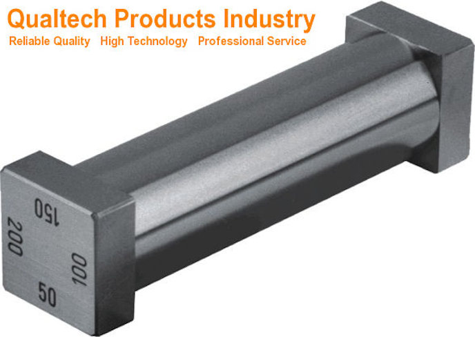

Cette norme, établie en 1945 et mise à jour en 2022, est supervisée par le Comité ASTM D01 sur les peintures et revêtements apparentés. Elle propose des méthodes spécifiques pour préparer des panneaux d'essai conformes aux exigences de l'industrie en matière d'uniformité d'épaisseur.
Vous trouverez des directives détaillées pour l'application de revêtements sur des panneaux d'essai, essentielles pour des tests de performance précis et l'évaluation de la qualité des peintures et produits similaires. Ces pratiques garantissent la fiabilité et la comparabilité des résultats de vos tests dans différents scénarios.
Points clés à retenir
- La norme décrit cinq méthodes distinctes pour appliquer des films de peinture uniformes sur des panneaux d'essai
- Vos résultats de test deviennent plus fiables lorsque vous suivez ces pratiques d'application standardisées
- L'uniformité de l'épaisseur de la peinture affecte directement la précision des tests de performance et du contrôle qualité
Portée de la norme ASTM D823-18
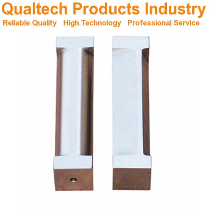

ASTM D823-18 Fournit des pratiques standard pour la création de films de peinture et de revêtement uniformes sur des panneaux d'essai. Ces pratiques vous aident à obtenir des résultats cohérents lors des tests des propriétés de la peinture.
La norme couvre trois méthodes principales d’application des revêtements :
- Méthode A:Applicateurs de film manuels
- Méthode B: Applicateurs de films mécaniques
- Méthode C: Équipement d'application par pulvérisation
Vous pouvez utiliser ces pratiques pour préparer des panels de test pour l’évaluation qualité de la peinture, durabilité et apparenceLes méthodes fonctionnent avec des peintures, des vernis, des laques et des matériaux de revêtement apparentés.
La norme relève du comité ASTM D01 sur les peintures et revêtements, matériaux et applications connexes. Le sous-comité D01.23 sur les propriétés physiques des films de peinture appliqués gère ces pratiques.
Ces pratiques vous aident à créer des éprouvettes d'épaisseur uniforme. Cette uniformité est essentielle pour tester avec précision les performances et les caractéristiques du revêtement.
Documents référencés
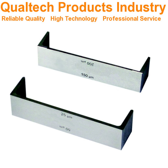

La norme ASTM D823-18 répertorie plusieurs normes et méthodes de test clés qui permettent de mesurer correctement l'épaisseur du film et de préparer les panneaux pour les tests de peinture et de revêtement.
Normes référencées
La méthode d'essai pour mesurer l'épaisseur du film sec références ASTM D1005, qui utilise des micromètres pour les revêtements organiques.
Vous devrez suivre la norme ASTM D609 lors de la préparation de panneaux en acier laminés à froid pour tester les peintures, les vernis et les revêtements de conversion.
Pour les mesures d’épaisseur de film humide, utilisez les méthodes de test ASTM D1212 spécialement conçues pour les revêtements organiques.
Ces normes fonctionnent ensemble pour garantir des procédures de test cohérentes et précises. Vous devez respecter les exigences spécifiques de chaque norme référencée pour maintenir des conditions de test adéquates et obtenir des résultats fiables.
Le texte en gras indique les normes critiques :
- ASTM D609 – Préparation des panneaux d’acier
- ASTM D1005 – Mesure du film sec
- ASTM D1212 – Mesure du film humide
Terminologie
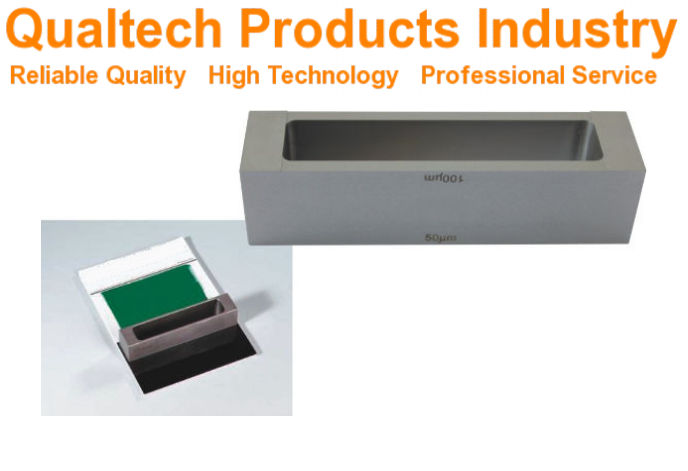

Les termes clés de la norme ASTM D823 aident les fabricants de peinture et les techniciens à créer des films de test uniformes à l'aide de méthodes d'application et de mesures standardisées.
Définitions des termes spécifiques à cette norme
Techniques d'application du film de peinture inclure retrait, où vous tirez la peinture sur une surface avec une lame ou une barre pour créer une épaisseur de revêtement uniforme.
Épaisseur du film Il s'agit de la profondeur mesurée du revêtement séché sur votre panneau d'essai. Vous devez maintenir une épaisseur constante sur toute la surface du panneau.
UN panneau de test il s'agit du matériau de substrat préparé, comme du métal ou du plastique, sur lequel vous appliquerez le revêtement pour évaluation.
Film uniforme Cela signifie que le revêtement présente une répartition uniforme et une épaisseur constante, sans zones plus épaisses ou plus fines que celles spécifiées. Cette uniformité est essentielle pour obtenir des résultats de test précis.
Application par pulvérisation automatisée utilise un équipement de pulvérisation contrôlé par machine pour appliquer des revêtements avec des réglages précis et répétables de pression, de distance et de vitesse.
Importance et utilisation
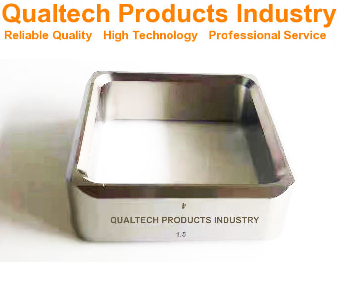

Pratiques ASTM D823 sont essentielles pour travailler avec des revêtements destinés à être appliqués par pulvérisation en usine ou sur le terrain. Ces méthodes vous permettent d'obtenir des résultats homogènes, que vous peigniez des objets en intérieur ou en extérieur.
Ces pratiques sont particulièrement importantes lorsqu'il s'agit d'évaluer l'aspect des revêtements métalliques. Cela inclut des tests de propriétés telles que la brillance et l'homogénéité des couleurs sur les surfaces.
Lors de l'application de revêtements selon ces méthodes de test, vous remarquerez peut-être une légère texture peau d'orange ou un motif de pulvérisation ondulé. Ce phénomène est normal et correspond à ce que l'on observe généralement dans les applications réelles.
Ces méthodes d'application normalisées Assurez-vous que vos résultats de test sont fiables et reproductibles. Vous pouvez les utiliser pour comparer différents produits de revêtement ou évaluer leurs performances dans diverses conditions.
La cinq pratiques distinctes Vous offre la flexibilité nécessaire pour choisir la méthode la plus adaptée à votre type de revêtement et à vos besoins de test. Chaque méthode vous permet d'obtenir une épaisseur de film uniforme, essentielle à la précision des tests et des évaluations.
Appareil
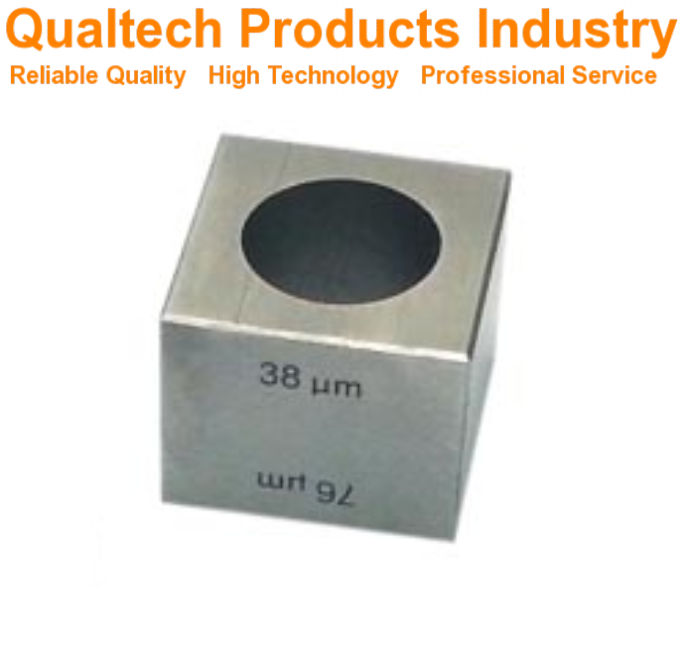

Un équipement et des outils appropriés sont essentiels pour produire des films de peinture et des revêtements uniformes sur des panneaux d'essai. Les exigences spécifiques relatives aux panneaux, aux outils d'application et aux équipements d'essai garantissent des résultats cohérents et fiables.
Spécifications du panneau de test
Les panneaux d'essai doivent être plats, rigides et propres pour obtenir une épaisseur de revêtement uniforme. Il est conseillé d'utiliser des panneaux en acier, en aluminium, en verre ou autre matériau. Matériaux approuvés par l'ASTM.
Les panneaux doivent présenter des dimensions précises, des bords droits et une surface exempte de défauts. Les dimensions standard des panneaux varient de 3 × 6 pouces à 6 × 12 pouces, selon vos exigences de test.
La préparation de la surface est essentielle. Nettoyez soigneusement les panneaux avec des solvants pour éliminer les huiles, la poussière et les contaminants avant l'application du revêtement.
Outils d'application de films
Cinq principales méthodes d'application sont utilisés pour créer des films uniformes :
- Machines de pulvérisation automatisées
- Enrobeuses par immersion motorisées
- Applicateurs de lames motorisés
- Pistolets pulvérisateurs portatifs
- Applicateurs manuels à lames
Chaque outil doit être correctement entretenu et calibré avant utilisation. Les équipements automatisés offrent une meilleure régularité que les méthodes manuelles.
Maintenez les buses de pulvérisation propres et correctement réglées. Remplacez régulièrement les lames et les applicateurs usés.
Équipement de conditionnement et d'essai
Votre zone de test nécessite des conditions de température et d'humidité contrôlées. Utilisez des thermomètres et des hygromètres calibrés pour surveiller l'environnement.
Les conditions standard exigent :
- Température : 23 ± 2°C
- Humidité relative : 50 ± 5%
Les jauges et appareils de mesure d'épaisseur de film doivent être correctement étalonnés. Stockez les panneaux horizontalement, à l'abri de la poussière, pendant le durcissement des films.
Utiliser des grilles de séchage adaptées qui ne perturbent pas le film humide. Surveiller les temps de séchage conformément aux spécifications du revêtement.
Échantillons d'essai
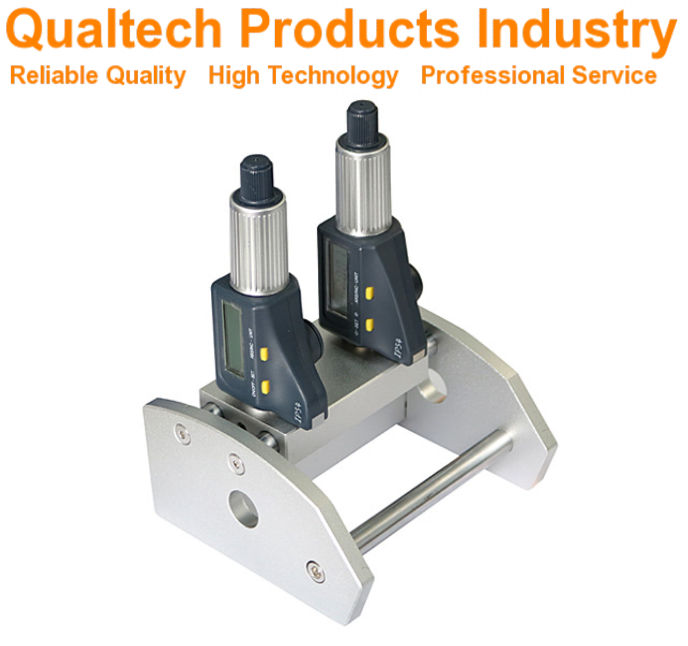

Une préparation adéquate des panneaux d'essai et des méthodes d'application du film sont essentielles pour obtenir des résultats précis d'évaluation des revêtements. Ces pratiques contribuent à garantir des tests cohérents et fiables des peintures et des revêtements.
Préparation des panneaux d'essai
Les panneaux d'essai doivent être propres et exempts de contaminants avant l'application du revêtement. Choisissez des panneaux en métal, en verre, en plastique ou en bois en fonction de vos exigences d'essai.
Nettoyer soigneusement les panneaux avec des solvants adaptés au matériau du support. Pour les panneaux métalliques, utiliser du white spirit ou de l'acétone pour éliminer les huiles et les résidus.
Poncez la surface si nécessaire pour obtenir une rugosité et une adhérence adéquates. Essuyez les panneaux avec un chiffon non pelucheux pour éliminer la poussière.
Directives de préparation du panel spécifier le maintien d'une température et d'une humidité constantes pendant la préparation, généralement 23°C ± 2°C et 50% ± 5% d'humidité relative.
Demande de film
Cinq pratiques standardisées Il existe des moyens pour appliquer des films de revêtement uniformes : machine de pulvérisation automatisée, machine de revêtement par immersion motorisée, lame motorisée, pistolet de pulvérisation manuel et techniques de tirage.
Choisissez votre méthode d'application en fonction du type de revêtement et de l'épaisseur de film souhaitée. Les méthodes automatisées offrent une meilleure répétabilité que les techniques manuelles.
Maintenir des conditions d’application appropriées :
- Température : 23°C ± 2°C
- Humidité relative : 50% ± 5%
- Débit d'air : Tirage minimal
- Position de la surface : horizontale ou verticale selon les spécifications
Laisser les films durcir dans des conditions contrôlées. Enregistrer la méthode d'application, les conditions et le temps de durcissement pour chaque échantillon.
Procédure
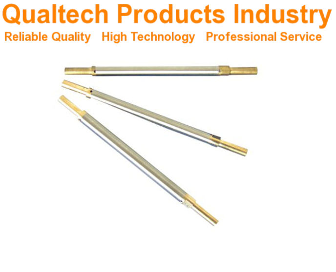

Le processus d'application de la peinture exige un contrôle rigoureux des conditions et des techniques pour obtenir des résultats d'essai de haute qualité. Le respect de méthodes normalisées garantit une épaisseur de film uniforme et une performance optimale du revêtement.
Conditions environnementales
Vous devez maintenir des niveaux de température et d'humidité spécifiques dans votre salle d'examen. Maintenez la température ambiante entre 23 °C ± 2 °C (73,4 °F ± 3,6 °F).
L'humidité relative doit rester entre 50% ± 5%. Vérifiez ces conditions au moins 24 heures avant de commencer le processus de demande.
Enregistrez les mesures environnementales au début et à la fin de chaque séance de revêtement. Cela permet de suivre toute variation susceptible d'affecter la formation du film.
Uniformité du revêtement
Appliquer le revêtement à l'aide d'un équipement de pulvérisation automatisé Pour des résultats plus homogènes, réglez le support du pistolet de pulvérisation pour qu'il se déplace à vitesse constante sur le panneau de test.
Maintenez une distance constante entre la buse de pulvérisation et la surface du panneau de test. La distance typique est de 15 à 20 cm.
Vérifiez l'épaisseur du revêtement lorsqu'il est encore humide à l'aide d'une jauge d'épaisseur de film humide. Effectuez plusieurs mesures sur la surface du panneau.
Recherchez tout signe de :
- Texture de peau d'orange
- Coule ou s'affaisse
- Couverture inégale
- Accumulation de bords
Séchage et durcissement
Positionnez les panneaux revêtus horizontalement pendant le séchage initial. Cela évite les coulures et assure une formation uniforme du film.
Gardez les panneaux à l’écart du flux d’air direct ou des sources de chaleur pendant les premières étapes du séchage.
Respectez les temps et températures de séchage recommandés par le fabricant. La plupart des revêtements nécessitent :
- 24 à 48 heures à température ambiante
- OR 30-60 minutes at elevated temperatures (specified by coating type)
Test the hardness and adhesion only after full cure. Early testing can damage the coating film.
Report

Proper reporting of test results from paint film thickness measurements ensures data accuracy and repeatability across different testing environments.
General Reporting Requirements
You must document all test conditions and methods used during the film thickness measurement process. Record the ambient temperature and relative humidity of the testing environment.
List all equipment used, including calibration dates and equipment identification numbers. Document any deviations from standard testing procedures.
Note the specific type and batch number of paint or coating tested. Include details about the test panel material, surface preparation methods, and application techniques used.
Test Results
Record film thickness measurements in micrometers or mils, taking multiple readings at specified points across the test panel surface. Include both individual measurements and calculated average values.
Note any defects, irregularities, or non-uniform areas observed in the coating film. Document visual observations of film quality, including surface texture and appearance.
Provide statistical analysis of measurement data when required, including standard deviation and variance. Include photographs or diagrams of measurement locations on test panels when needed for clarity.
Precision and Bias


ASTM D823-18 does not include specific precision and bias data for the described practices. This is because the method focuses on preparation techniques rather than measurement results.
The precision of your film thickness will depend heavily on your equipment calibration and skill level. You need to maintain proper calibration of all measuring devices and applicators.
Regular verification of your test panels and application methods helps ensure consistent results. You should check your procedures against the ASTM D823 standard practices to maintain quality.
Common factors affecting precision include:
- Environmental conditions
- Application technique
- Equipment maintenance
- Panel preparation quality
- Film applicator condition
Your coating thickness measurements must be made according to appropriate ASTM standards for the specific type of coating being tested. This ensures your results can be compared with other labs following the same procedures.
When you report results, note any deviations from standard practices that might affect the uniformity of the film thickness. Keep detailed records of application conditions and methods.
Keywords

Paint films, coatings, test panels, film thickness, application methods, paint thickness testing, film uniformity.
ASTM D823-18 falls under the scope of ASTM Committee D01 on Paint and Related Coatings, Materials, and Applications.
The specific subcommittee responsible for this standard is D01.23 which focuses on Physical Properties of Applied Paint Films.
These standard practices were first established in 1945 and the current version was approved in 2022.
Key terms you’ll encounter in this standard include:
- Film application
- Coating thickness
- Test panel preparation
- Uniform film production
- Paint application methods
- Quality control testing
- Surface preparation
Questions fréquemment posées

The ASTM D823-18 standard covers specific practices for creating uniform paint and coating films on test panels through multiple application methods. These practices address equipment requirements, process variables, safety protocols, and quality control measures.
What is the scope of ASTM D823-18 and what does it cover regarding film application?
Five distinct practices make up ASTM D823-18, each focused on producing uniform coating thickness on test panels. These practices include automated spray application, motor-driven dip coating, and other specialized methods.
The standard applies to paints, varnishes, and related coating materials used in testing and quality control applications.
Can you explain the methodologies outlined in ASTM D823-18 for achieving uniform thickness?
The standard specifies automated spray machines as one primary method for achieving consistent film thickness.
You must maintain precise control over application speed, distance, and material flow rate during the coating process.
Dip coating requires controlled immersion and withdrawal rates to ensure even coverage.
How does ASTM D823-18 differ from ASTM D3258 in terms of film application?
ASTM D823-18 focuses specifically on creating uniform thickness films for testing purposes. It emphasizes automated and mechanical application methods.
D3258 deals more broadly with paint film evaluation and includes different testing parameters.
What are the equipment requirements specified in ASTM D823-18 for preparing test panels?
You need calibrated automated spray equipment or dip coating machinery that can maintain consistent speeds and distances.
The test panels must meet specific cleanliness and surface preparation standards.
Your equipment must be able to control application parameters like pressure and flow rate precisely.
What variables should be controlled during the application process as per ASTM D823-18?
Temperature and humidity in your testing area need strict monitoring and control.
Material viscosity and application speed require consistent measurement and adjustment.
Distance between spray equipment and test panels must remain uniform throughout the process.
What are the safety considerations to keep in mind when following ASTM D823-18 practices?
You must use proper ventilation when working with paint and coating materials.
Personal protective equipment including respiratory protection, gloves, and eye protection is essential.
Keep all equipment properly grounded to prevent static electricity buildup.
- Published in Normes d'essai ASTM, Science and Research
- 1
- 2